Method and apparatus for providing tactile message

a technology of providing method and tactile message, which is applied in the direction of instruments, messages/mailboxes/announcements, and details of portable computers, etc., can solve the problems of limited service providing the conventional tactile sense, limited range of emotions or feelings of users, and limited range of emotions or feelings to convey

Active Publication Date: 2020-12-08
CK MATERIALS LAB
View PDF23 Cites 0 Cited by
  • Summary
  • Abstract
  • Description
  • Claims
  • Application Information

AI Technical Summary

Benefits of technology

[0010]According to the present invention configured as described above, as the tactile sense is transmitted, the existing message service relying primarily on visual perception is avoided and the emotions that users feel in various situations allow other person to feel the same way.
[0011]In addition, according to the present invention, as promptly inputting a feeling of a sender in a tactile pattern, various tactile feelings such as vibration, squeeze, tightening, hitting, pushing, tapping, or tilting are more sensitively transmitted to a receiver.

Problems solved by technology

Short Message Service (SMS) among existing communication services using a wireless communication terminal allows the user to conveniently contact and communicate with each other in real time, but has limitations in transmitting the emotion or feeling of the user.
However, most of these tools are also visual, so that it has limitations in conveying rich emotions and feelings of users.
In addition, the service providing the conventional tactile sense is mostly limited to the vibration, and there is a problem that it is monotonous because it may not give direction to the tactile sense.
In addition, since each tactile feedback pre-stored in the memory unit is read and transmitted, it is not sufficient to transmit a tactile sense reflecting user's emotions or emotions in real time.

Method used


Image

  • Method and apparatus for providing tactile message
  • Method and apparatus for providing tactile message
  • Method and apparatus for providing tactile message

Examples


first embodiment

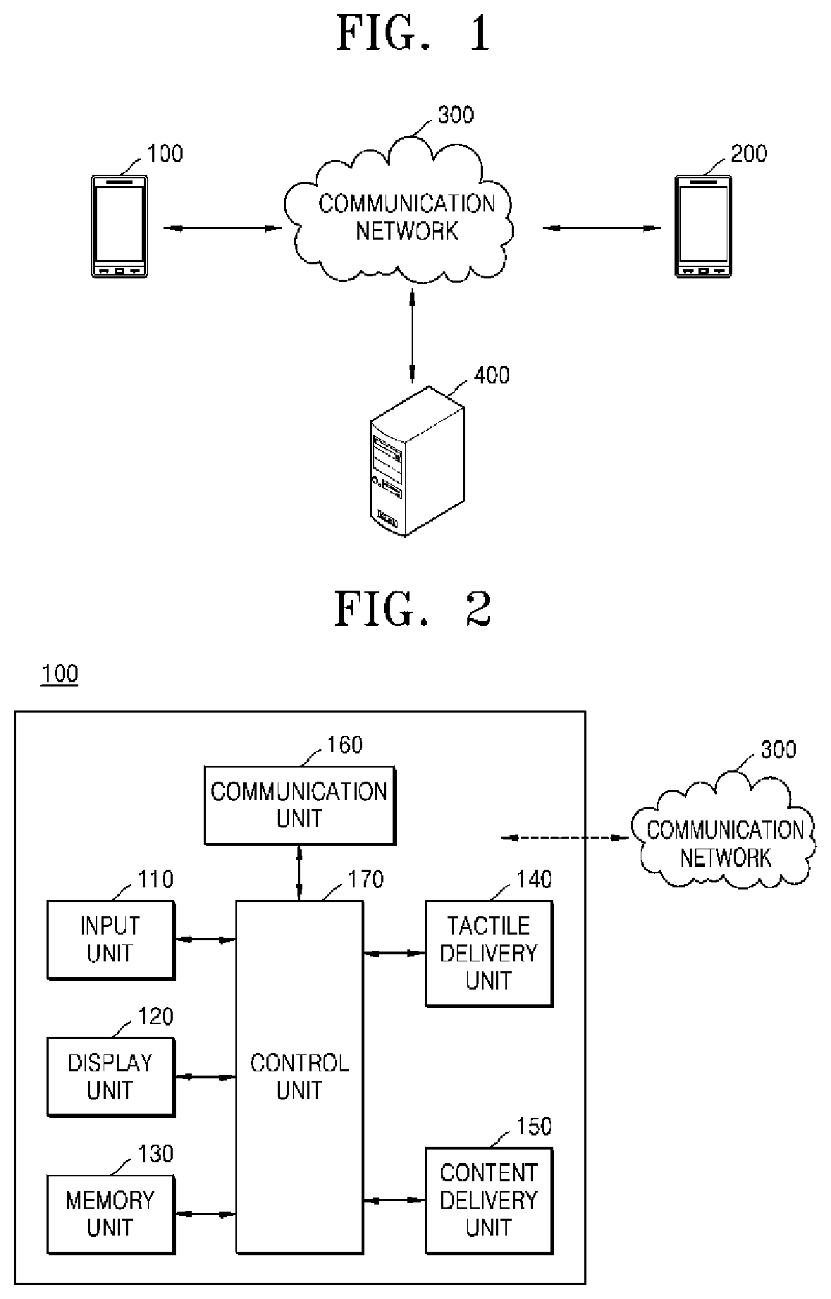
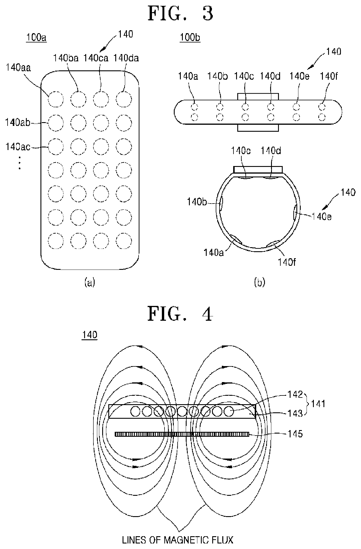
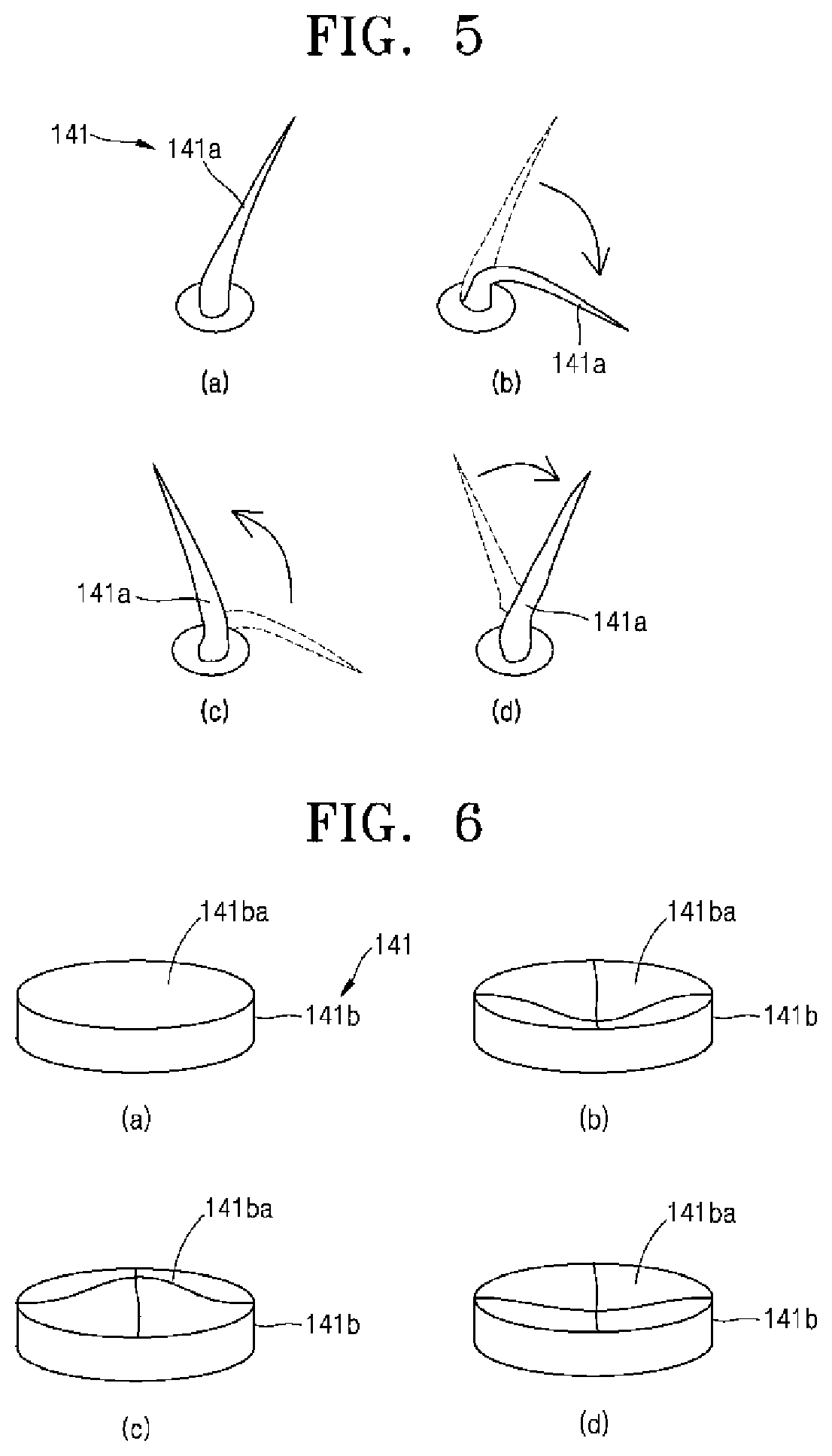
[0086]FIG. 5 is a view showing the tactile delivery unit 140 according to the present invention.

[0087]Referring to FIG. 5, the tactile unit 141 of the tactile delivery unit 140 according to the first embodiment may have the shape of a fine protrusion 141a. In order to convey the tactile feeling in detail and emotionally, the fine protrusion 141a may have a thickness of about 25 μm or less so as to be similar to fleece or the like, or about 100 μm or less so as to be similar to human hair or the like.

[0088]As shown in (a) of FIG. 5, the fine protrusion 141a may maintain a slightly inclined shape (first shape) when it is not affected by the external magnetic field. Of course, it is also possible to have a fine protrusion shape erected vertically without tilting. Next, as shown in (b) of FIG. 5, in the case of being influenced by an external magnetic field, the fine protrusions 141a may be more inclined or maintain a lying shape (second shape). Next, as shown in (c) and (d) of FIG. 5, ...

second embodiment

[0089]FIG. 6 is a view showing the tactile delivery unit 140 according to the present invention.

[0090]Referring to FIG. 6, the tactile unit 141 of the tactile delivery unit 140 according to the second embodiment includes a hollow cylindrical body 141b, a dome or a polyhedron (see (b) of FIG. 7).

[0091]As shown in (a) of FIG. 6, in a case where it is not affected by the external magnetic field, the cylinder 141b in which the inside is hollow may exhibit a flat shape (first shape) of the upper surface 141ba. Next, as shown in (b) of FIG. 6, in the case of being influenced by an external magnetic field, the cylinder 141b may show a shape (second shape) in which the upper surface 141ba is recessed into an empty space. Next, as shown in (c) and (d) of FIG. 6, when the application of the magnetic field is released and is not affected by the external magnetic field, in relation to the cylinder 141b, the upper surface 141ba may be reciprocated by their own elasticity (or resilience) while re...

third embodiment

[0099]The tactile unit 141c is in the form of a plate and the support member 141ca is integrally provided on both sides of the tactile unit 141c in a curved shape. The support member 141ca is provided between the insulator 144 and the tactile unit 141c to secure a space in which the tactile unit 141c or the support member 141ca may operate. For example, the tactile unit 141c and the support member 141ca move upward and downward in the space by the magnetic field generated by the magnetic field generation unit 145, and perform a reciprocating motion to change the shape. This shape change may move one cell or the entire cell, and as a result, the user may convey various tactile feelings such as vibration, beating, and tapping.


PUM


Abstract

The present invention relates to a tactile message providing method and a tactile message providing device. Embodiments of the present invention provide a tactile message providing method for a tactile sense in a mobile communication terminal device, the method including: (a) driving a tactile message program; (b) receiving a tactile pattern; (c) converting the tactile pattern into a pattern signal; and (d) transmitting the pattern signal to a reception terminal device, wherein the tactile message program includes a tactile pattern input window or a tactile switch icon for switching a text input window to a tactile pattern input window, wherein the pattern signal is a signal capable of transmitting tactile information by operating a tactile delivery unit of the reception terminal device.

Description

TECHNICAL FIELD[0001]The present invention relates to a tactile message providing method and a tactile message providing device. More particularly, the present invention relates to a tactile message providing method and a tactile message providing device that may provide tactile information to a counterpart in real time by a user inputting a tactile pattern or selecting a applpreviously stored tactile pattern.BACKGROUND ART[0002]As the supply rate of the wireless communication terminal increases, it becomes a necessity of life of modern people and is developed as a wearable type device which may be worn by the user in the existing handheld type.[0003]Also, in terms of communication services, it evolves from existing voice calls and short messages and evolves toward providing multimedia services including various data transmission and various additional services.[0004]Short Message Service (SMS) among existing communication services using a wireless communication terminal allows the ...

Claims


Application Information

Patent Timeline
Patent Type & Authority Patents(United States)
IPC IPC(8): G06F3/0488G06F3/01G06F3/046H04W4/14G06F1/16G06F3/041
CPCG06F3/0416G06F3/017G06F3/04883G06F1/1626G06F3/046G06F1/163G06F3/016H04W4/14G06F2203/014H04L51/04H04L51/10H04L51/18H04L51/07G06F3/0488G06F3/04817
Inventor KIM, HYEONG JUNLEE, JONG HUNKIM, NAM SEOKLEE, JEONG BUM
Owner CK MATERIALS LAB
Why Eureka
Try Eureka