
Multistage pump

a multi-stage pump and pump technology, applied in non-positive displacement pumps, liquid fuel engines, mechanical devices, etc., can solve the problems of high price of the pump and inevitable stability problems of the pump, and achieve the effect of sufficient stability and robustness

Active Publication Date: 2021-01-26
GRUNDFOS HLDG
View PDF7 Cites 0 Cited by
  • Summary
  • Abstract
  • Description
  • Claims
  • Application Information

AI Technical Summary

Benefits of technology

The present invention provides a multistage pump that is light-weight, stable, and robust. This is achieved by using an elongate carrier, such as a pipe, that is mechanically connected to the pump body and runs through the base element, providing stability to the inlet and outlet ports. This design ensures high stability in all directions across the pipe and creates channels for the inlet and outlet ports. Compared to pumps with cast iron base elements, the present invention is more cost-effective.

Problems solved by technology

However, the use of cast iron for the base element, on the one hand, imparts a certain weight to the pump and, on the other hand, also renders the pump expensive due to high material costs.
However, when replacing cast iron by sheet metal in the base element, the pump inevitably will suffer from stability problems.

Method used


Image

  • Multistage pump
  • Multistage pump
  • Multistage pump

Examples


Embodiment Construction

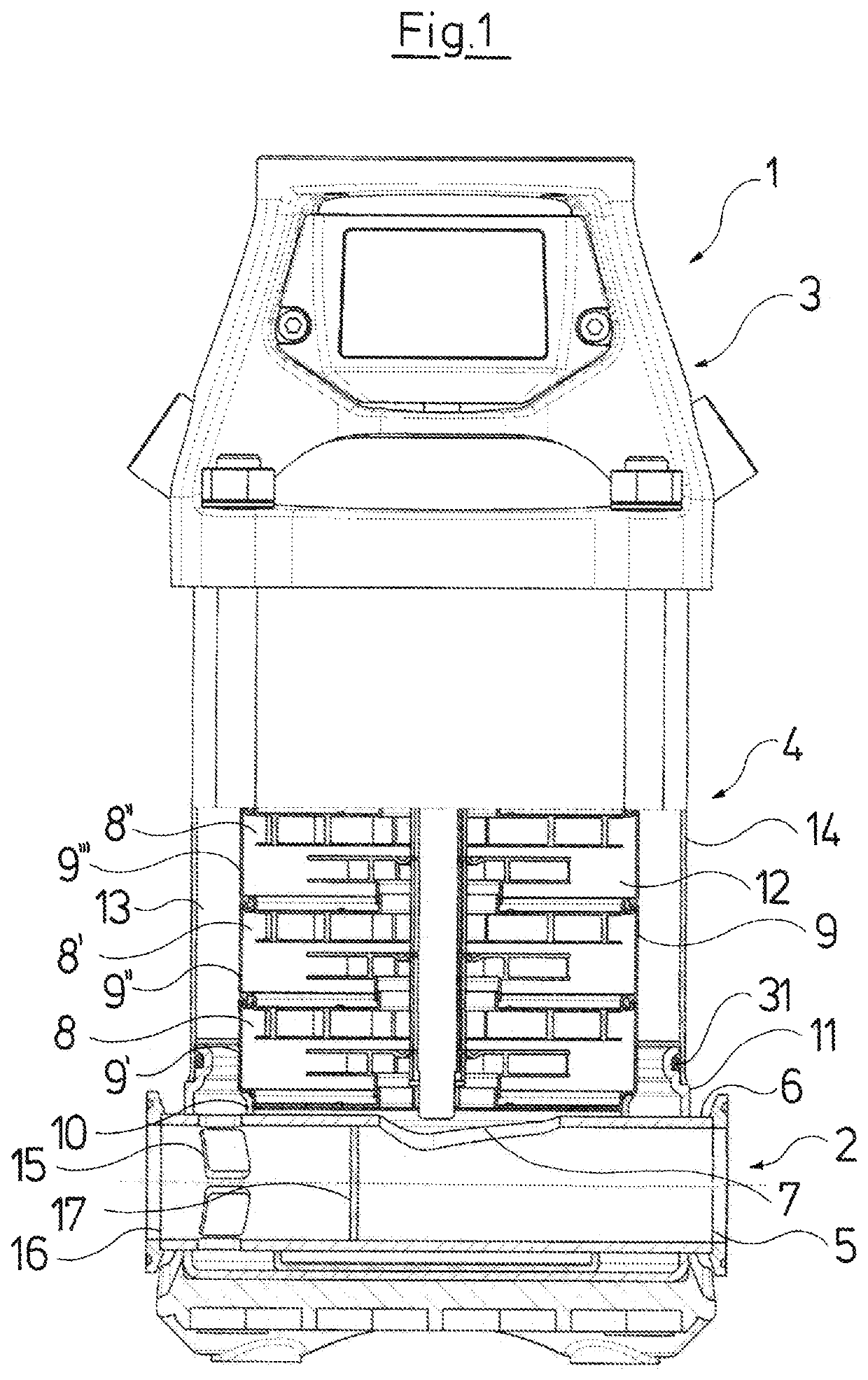
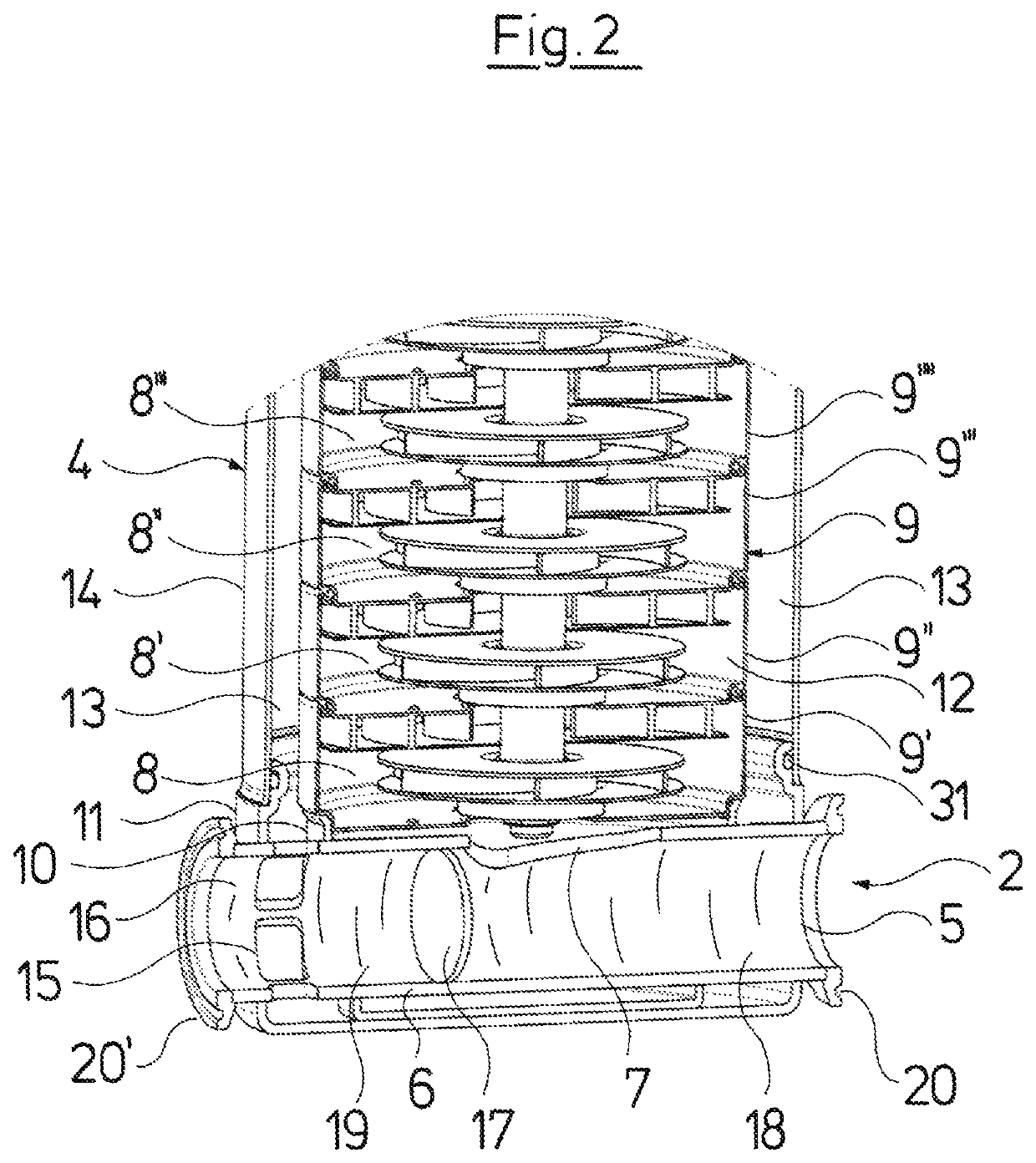
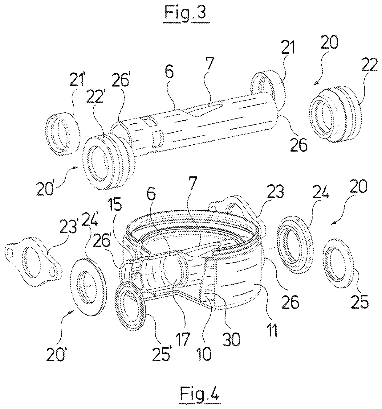
[0031]Referring to the drawings, FIG. 1 shows a multistage pump 1 according to a preferred embodiment of the invention, whereby the lower half of the pump 1 is shown in sectional view and the upper half in regular side view. As can be seen, basically the pump 1 can be subdivided in three sections, namely, the lowermost part of the pump 1 is formed by the base element 2, the uppermost part of the pump 1 is formed by a head element 3, and in between the base element 2 and the head element 3, there is arranged a pump body 4. When the pump 1 is activated, fluid, or in particular, water, enters the pump 1 through an inlet port 5 in the base element 2, then passes through a pipe 6 so as to enter through a first hole 7 of the pipe 6 the pump body 4 in which a plurality of pump stages 8, 8′, 8″, etc. are provided, each having an impeller and an diffuser.

[0032]In the pump body 4, the fluid is passed on from stage to stage upwards within a first annular space 12 surrounded by an inner pipe 9 ...


PUM

PropertyMeasurementUnit
pressureaaaaaaaaaa
circumferenceaaaaaaaaaa
diameteraaaaaaaaaa

Abstract

The invention relates to a multistage pump (1), including a pump body (4), at a lower end of which a base element (2) is arranged, and at an upper end of which a head element (3) is arranged. At least the base element (2) is made from sheet steel and has an inlet port (5) and an outlet port (16). The inlet port (5) and the outlet port (16) are mechanically connected to each other by a pipe (6) running through the base element (2).

Description

CROSS REFERENCE TO RELATED APPLICATIONS[0001]This application claims the benefit of priority under 35 U.S.C. § 119 of European Application 15 197 535.6 filed Dec. 2, 2015, the entire contents of which are incorporated herein by reference.FIELD OF THE INVENTION[0002]The present invention relates to a multistage pump comprising a pump body at a lower end of which a base element is arranged, and at an upper end of which a head element is arranged, at least the base element being made from sheet steel and having an inlet port and an outlet port.BACKGROUND OF THE INVENTION[0003]Multistage rotary pumps known in prior art basically comprise a base element, a pump body, and a head element as main elements. The base element is provided with an inlet port equipped with a suction connecting piece through which a fluid enters the pump, and an outlet port equipped with a pressure connecting piece through which the fluid, after having been passed through a plurality of pump stages arranged one ab...

Claims


Application Information

Patent Timeline
Patent Type & Authority Patents(United States)
IPC IPC(8): F04D29/42F04D29/02F04D1/06F04D29/62
CPCF04D29/4266F04D1/06F04D1/063F04D29/026F04D29/4293F04D29/628F05D2230/54F05D2250/51F05D2250/52F05D2300/171F16L25/00
Inventor MIKKELSEN, STEEN
Owner GRUNDFOS HLDG
Learn More