
MR radio-frequency shielding unit

a radio-frequency shielding and unit technology, applied in the field can solve the problems of radio-frequency shielding units, significantly higher losses, and significantly lower attenuating effects on external interference of magnetic resonance apparatuses, so as to reduce the coupling of interference, improve the mechanical protection, and facilitate access

Active Publication Date: 2020-01-14
SIEMENS HEALTHCARE GMBH
View PDF14 Cites 0 Cited by
  • Summary
  • Abstract
  • Description
  • Claims
  • Application Information

AI Technical Summary

Benefits of technology

The solution provides improved radio-frequency shielding efficiency and interference attenuation for magnetic resonance apparatuses with low main magnetic field B0, minimizing heating and image artifacts while maintaining mechanical robustness.

Problems solved by technology

The fields from the eddy currents may extend even into the patient and cause there image interference and / or image artifacts in a magnetic resonance measurement.
Coupled-in noise (e.g., in the form of field spikes) that may be caused by switching pulses of gradient amplifiers, for example, may present another problem.
In the past, radio-frequency shielding units of such a design have been well-suited to magnetic resonance apparatuses in which the main magnetic field B0 has a strength of typically 1.5 or 3 T. Such radio-frequency shielding units, however, exhibit significantly higher losses and significantly lower attenuating effects on external interference for magnetic resonance apparatuses in which the main magnetic field B0 is of lower strength (e.g., less than 1 T).

Method used


Image

  • MR radio-frequency shielding unit
  • MR radio-frequency shielding unit
  • MR radio-frequency shielding unit

Examples


Embodiment Construction

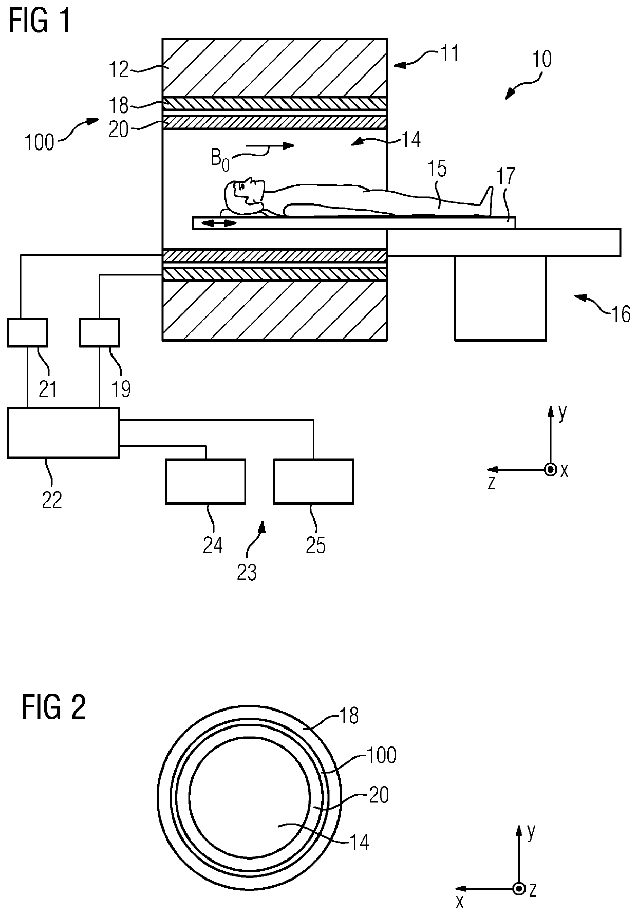
[0060]FIG. 1 is a schematic representation of one embodiment of a magnetic resonance apparatus 10. The magnetic resonance apparatus 10 includes a magnet unit 11. The magnet unit 11 includes a main magnet 12 for producing a powerful main magnetic field B0 that, for example, is constant over time. The magnetic resonance apparatus 10 also includes a patient placement zone 14 for accommodating a patient 15. The patient 15 may be moved into the patient placement zone 14 by a patient support apparatus 16 of the magnetic resonance apparatus 10. The patient support apparatus 16 includes, for this purpose, a patient couch 17 that is configured to be able to move inside the patient placement zone 14.

[0061]The magnet unit 11 further includes a gradient coil unit 18 for generating magnetic field gradients that are used for spatial encoding during imaging. The gradient coil unit 18 is controlled by a gradient control unit 19 of the magnetic resonance apparatus 10. The magnet unit 11 also include...


PUM


Abstract

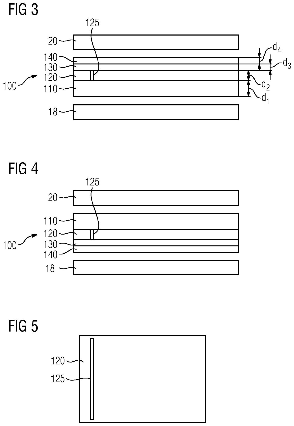
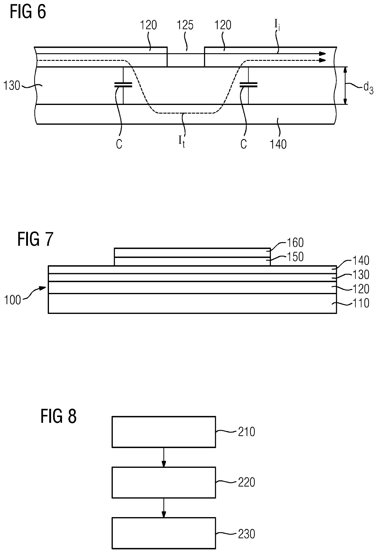
A radio-frequency shielding unit for shielding a radio-frequency antenna unit of a magnetic resonance apparatus and a magnetic resonance apparatus are provided. The radio-frequency shielding unit includes a support layer, a first conducting layer, an insulating layer, and a second conducting layer. The first conducting layer is arranged between the support layer and the insulating layer, and the insulating layer is arranged between the first conducting layer and the second conducting layer.

Description

[0001]This application claims the benefit of European Application No. EP17176031.7, filed on Jun. 14, 2017, which is hereby incorporated by reference in its entirety.BACKGROUND[0002]The present embodiments relate to a radio-frequency shielding unit for shielding a radio-frequency antenna unit of a magnetic resonance apparatus and to a magnetic resonance apparatus.[0003]Magnetic Resonance Imaging (MRI) is a known technique for producing magnetic resonance images of a patient and is based on the physical phenomenon of magnetic resonance (MR). This technique uses a radio-frequency antenna unit to radiate excitation pulses into the patient during a magnetic resonance measurement in order to trigger magnetic resonance signals. For spatial encoding of the magnetic resonance signals, the magnetic resonance apparatus also includes a gradient coil unit that is used to generate magnetic field gradients. The magnetic field gradients are superimposed on a static main magnetic field B0 that is g...

Claims


Application Information

Patent Timeline
Patent Type & Authority Patents(United States)
IPC IPC(8): G01V3/00G01R33/422H01Q7/00H01Q1/52G01R33/34
CPCG01R33/422H01Q7/00G01R33/34007H01Q1/526G01R33/421G01R31/34A61B5/055H01F27/36G01R33/3856G01R29/0835G01R3/00
Inventor EBERLER, LUDWIGNISTLER, JÜRGENVESTER, MARKUS
Owner SIEMENS HEALTHCARE GMBH
Learn More