
Centrifugal pump

a centrifugal pump and centrifugal technology, applied in the direction of check valves, liquid fuel engines, functional valve types, etc., can solve the problems of only being exchanged as a whole, known non-return valves in particular can have problems in regard to sealing, etc., to reduce construction height, increase the stability of the shut-off body, and reduce the cost of manufactur

Active Publication Date: 2019-04-30
GRUNDFOS HLDG
View PDF12 Cites 0 Cited by
  • Summary
  • Abstract
  • Description
  • Claims
  • Application Information

AI Technical Summary

Benefits of technology

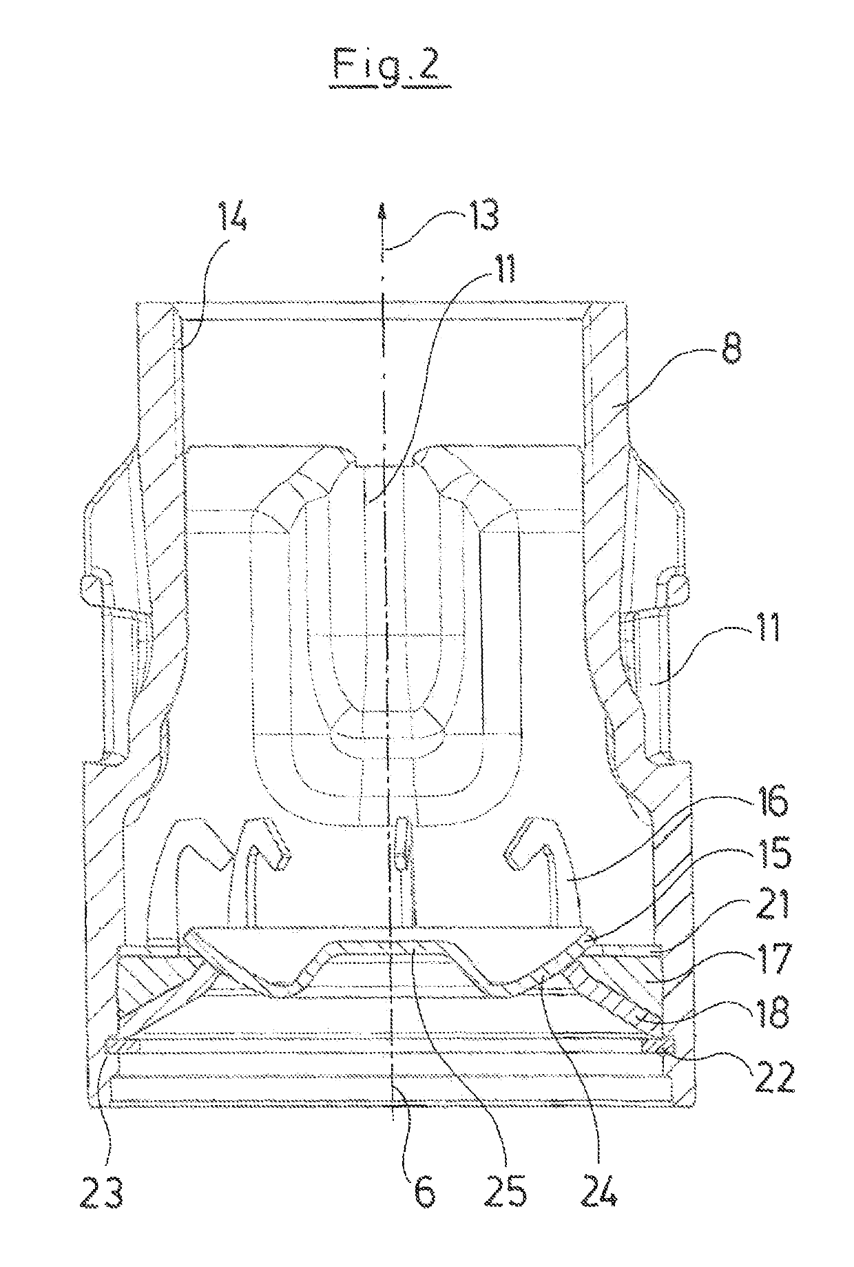
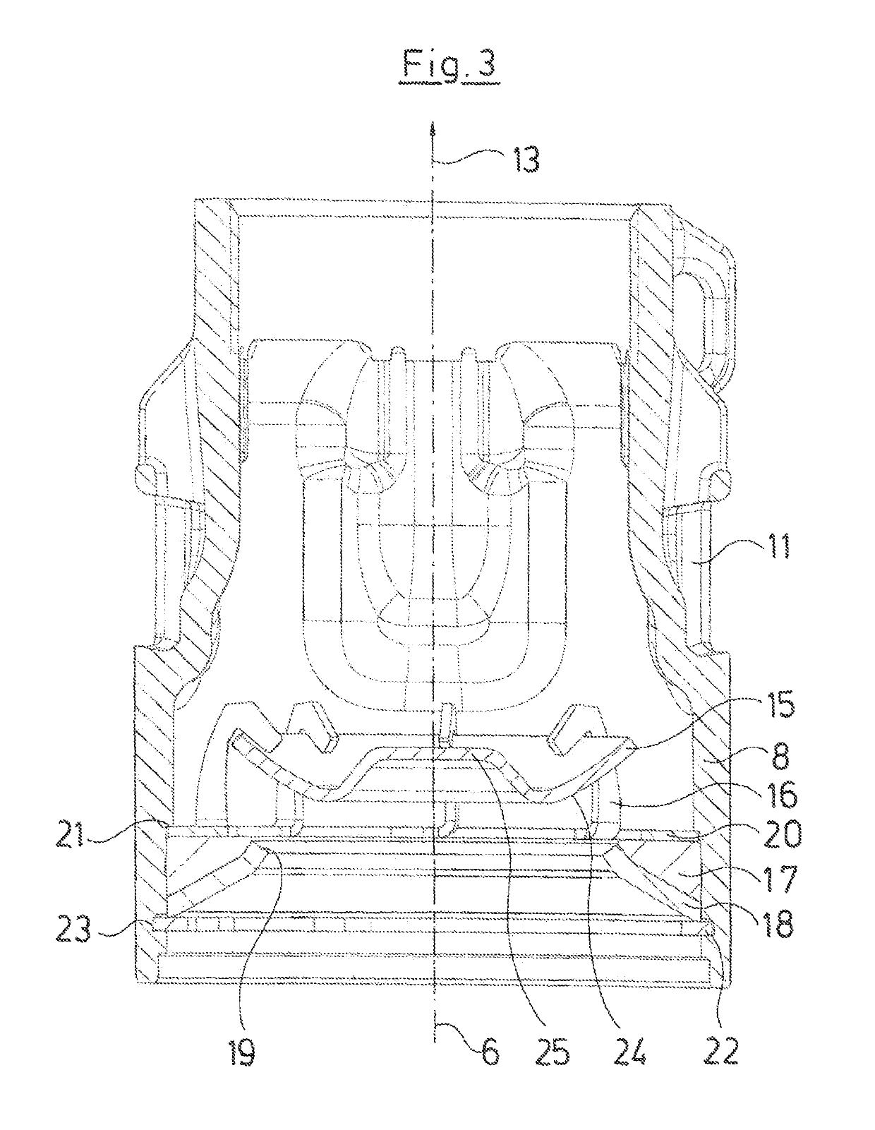
The present invention aims to design a guide for a valve that allows the shut-off body to move from the closure position into the opened position without tilting or canting. The guide is designed inwardly tapering, so that the shut-off body can move freely and without friction. The inner contour of the guide is designed to ensure the shut-off body assumes a predefined position on the valve seat, regardless of the pump's position. The guide also allows for a low-loss flow in the middle region, which is achieved by designing a part-circle-shaped region in the guide. The shut-off body is made of a thin plate shaped from sheet-metal and has a central boss for increased stability and reduced construction height. The technical effects of the invention are improved stability, reduced construction height, and improved flow performance.

Problems solved by technology

In lying operation, the known non-return valve in particular can have problems with regard to the sealedness, if the valve plate comes to bear on the sealing seat in a non-centered manner due to gravity.
Moreover, the non-return valve can only be exchanged as a whole, since neither the seal nor the component receiving this or the valve plate can be removed from the valve housing which is designed as a closed welded construction.

Method used


Image

  • Centrifugal pump
  • Centrifugal pump
  • Centrifugal pump

Examples


Embodiment Construction

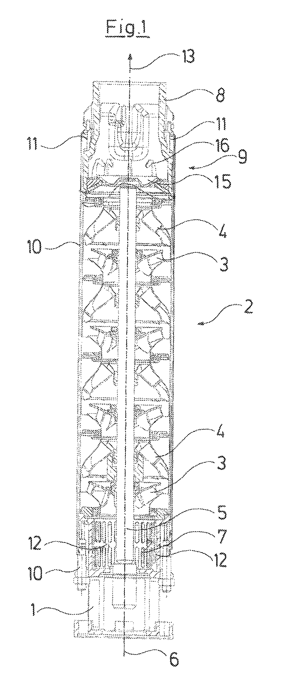
[0034]With the pump represented by way of FIG. 1, the drive motor which is necessary for operation is not shown and this in the representation according to FIG. 1 connects at the bottom to a coupling 1 which connects the drive motor and the pump 2 to one another. The pump 2 here comprises four pump stages which are hydraulically connected one after the other, in each case consisting of a pump impeller 3 and a diffuser 4 which is connected downstream of this in the flow direction. The pump impellers 3 are driven via a common shaft 5 which ends at the upper side of the uppermost diffuser 4 and at the lower side reaches to up to the coupling 1 where it is designed for the rotationally fixed connection to the free shaft end of the drive motor. The housing is formed by sheet-metal forming parts in the region of the pump impellers 3 and the diffusers 4, as is counted as belonging to the state of the art, and in this context the corresponding well pumps of the type Grundfos SP 30 are refer...


PUM


Abstract

The multi-stage submersible pump at the exit side is provided with a non-return valve (9) including a valve seat (19) and a shut-off body (15) which is movably arranged thereto in a limited manner and which is arranged with a positive fit and in a movable manner within a guide (16) surrounding the shut-off body (15) with play. The inner contour of the guide (16) tapers inwards towards the valve seat (19), counter to the main flow direction (13).

Description

CROSS REFERENCE TO RELATED APPLICATIONS[0001]This application claims the benefit of priority under 35 U.S.C. § 119 of European Patent Application EP 14 169 581.7 filed May 23, 2014, the entire contents of which are incorporated herein by reference.FIELD OF THE INVENTION[0002]The invention relates to a centrifugal pump, in particular to a multi-stage submersible pump, with a non-return valve with a valve seat and with a shut-off body which is movably arranged thereto in a limited manner, wherein the shut-off body is arranged with a positive fit and in a movable manner within a guide which surrounds the shut-off body with play.BACKGROUND OF THE INVENTION[0003]With centrifugal pumps, it is counted as belonging to the state of the art to integrate a non-return valve within the pump, in order to prevent delivered fluid from being able to flow back through the pump. Such a non-return valve in particular is envisaged with multi-stage submersible pumps, in order to prevent a backflow throug...

Claims


Application Information

Patent Timeline
Patent Type & Authority Patents(United States)
IPC IPC(8): F16K15/02F04D13/08F04D15/00F04D1/12F04D29/22F04D29/44F04D29/42F04D29/08F04D29/62
CPCF16K15/023F04D1/12F04D13/08F04D15/0083F04D29/628F04D29/22F04D29/426F04D29/445F04D29/086
Inventor SORENSEN, THOMASHOPFNER, DANIEL
Owner GRUNDFOS HLDG
Learn More