
Drive module with decoupling element

a technology of decoupling element and drive module, which is applied in the direction of machines/engines, liquid fuel engines, magnetic circuit shapes/forms/construction, etc., can solve the problems of less flexible use and larger size of the drive module, and achieve the effect of a wider structural scop

Active Publication Date: 2015-01-06
ROBERT BOSCH GMBH
View PDF10 Cites 0 Cited by
  • Summary
  • Abstract
  • Description
  • Claims
  • Application Information

AI Technical Summary

Benefits of technology

The drive modules described in this patent text can be used in a variety of applications, such as in a motor vehicle fan system. These modules are designed to be easily installed and disassembled, which improves accessibility and reduces installation time. The design also allows for a more compact construction, as there is no need to position decoupling elements in the axial or radial direction. The stator can be mounted on the drive module with a frictional connection, making it easier to handle in production. The fan module is particularly compact, which allows for more space to be freed up in other parts of the motor vehicle. The technical effects of this patent text are improved installation and disassembled time of fans in motor vehicles, as well as improved structural scope for other components.

Problems solved by technology

As a consequence of this, the resulting drive module is larger and less flexible in terms of its use.

Method used


Image

  • Drive module with decoupling element
  • Drive module with decoupling element
  • Drive module with decoupling element

Examples


Embodiment Construction

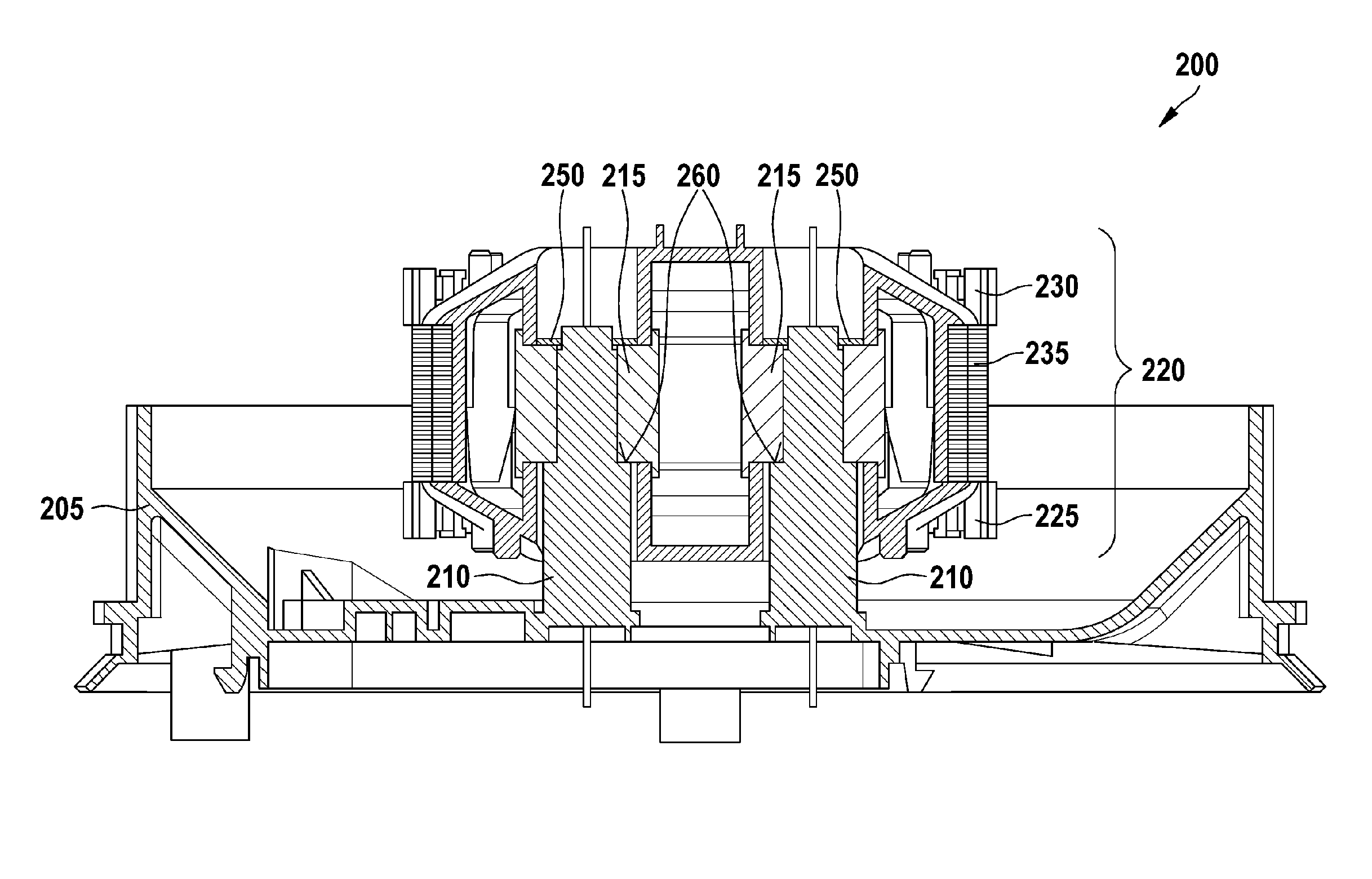
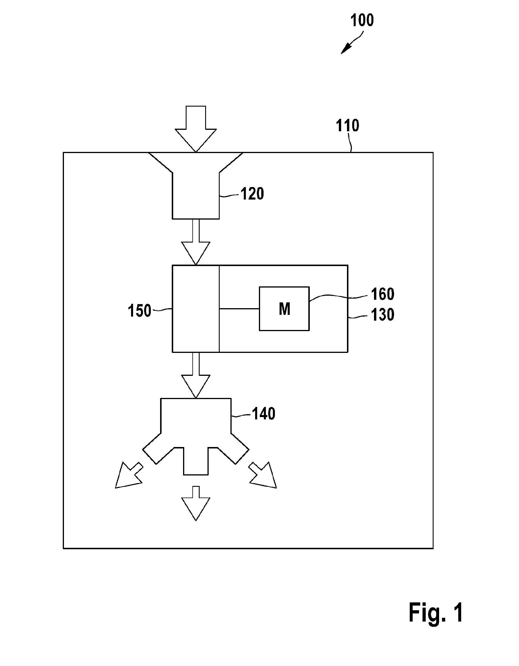
[0021]FIG. 1 shows a diagrammatic illustration of a motor vehicle fan system 100. A motor vehicle 110 comprises an intake section 120, a fan module 130 and a distributor section 140. The fan module 130 comprises a fan wheel 150 and a drive module 160. Optional elements of the motor vehicle fan system 100 are not contained in the illustration of FIG. 1, such as filters, flaps, valves, heat exchangers, condensers and the like which are not further relevant in the present context. The drive module 160 sets the fan wheel 150 in rotation, with the result that air is sucked into the fan wheel 150 from an outer side of the motor vehicle 110 through the intake section 120 and is subsequently conveyed through the distributor section 140 to the inside of the motor vehicle 140. A use of the fan module 130 in a ventilation system outside a motor vehicle 110 is likewise possible.

[0022]The intake section 120 and the distributor section 140 are frequently configured jointly in a common section. Th...


PUM


Abstract

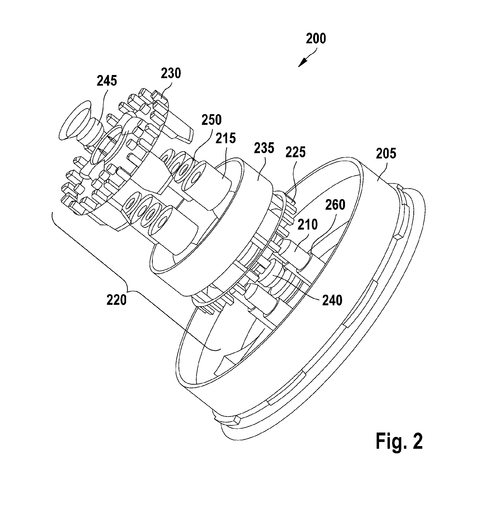
The invention relates to a drive module, particularly for a fan in a motor vehicle, comprising a drive motor having a stator, at least one vibration-dampening decoupling element, and a fastening flange connected to the stator of the drive motor by the decoupling element, wherein the decoupling element is arranged in the interior of the stator and the fastening flange comprises a supporting element that is engaged in the decoupling element.

Description

[0001]The invention relates to a drive module; in particular, the invention relates to a drive module for a fan in a motor vehicle.[0002]Drive modules are standardized assemblies which can be handled separately and can be used universally. One field of use of a drive module of this type is a fan system in a motor vehicle, in which a fan is arranged between an intake section for fresh air and a distributor section for delivered air. A fan of this type can be constructed with the aid of a drive module, with the result that an installation and dismantling time of the fan is minimized and, in addition, accessibility of components which are situated in the adjacent sections, for example of a heat exchanger or a heater, is improved.[0003]In drive modules in general and in a drive module for use in a fan, in particular, decoupling of the drive motor from its surroundings with regard to vibrations of every type is frequently required, in order to minimize solid-borne sound and vibrations wh...

Claims


Application Information

Patent Timeline
Patent Type & Authority Patents(United States)
IPC IPC(8): H02K5/24F04D25/06F04D29/42F04D29/66H02K7/14
CPCF04D29/668F04D25/0613F04D29/4226H02K5/24H02K7/14
Inventor MUELLER, ANDREASSCHIEL, ANDREASEISENHARDT, HARALDLUDWIG, MATTHIAS
Owner ROBERT BOSCH GMBH
Learn More