
Diving fins

a technology of diving fins and fins, which is applied in the field of diving fins, can solve the problems of less than optimal aquatic kicking efficiency, increased stiffness, lack of smoothness, and increased fatigue, and achieves efficient strength conservation, improved flutter kicking efficiency, and improved speed performance.

Inactive Publication Date: 2005-04-26
HU CHIA TE
View PDF2 Cites 2 Cited by
  • Summary
  • Abstract
  • Description
  • Claims
  • Application Information

AI Technical Summary

Benefits of technology

"The invention provides improved diving fins with several improvements. Firstly, the fins have a front section thinner than the rear section, which allows for better efficiency in kicking and swimming. Secondly, there are adjusting flukes that can be cut to change the length of the swinging of the fins, allowing for different physical strengths and ages of individuals. Lastly, there is a conical transversal fluke on the rear section of the fins that guides water smoothly forward, resulting in higher kicking efficiency. These improvements make the fins more effective and comfortable for divers."

Problems solved by technology

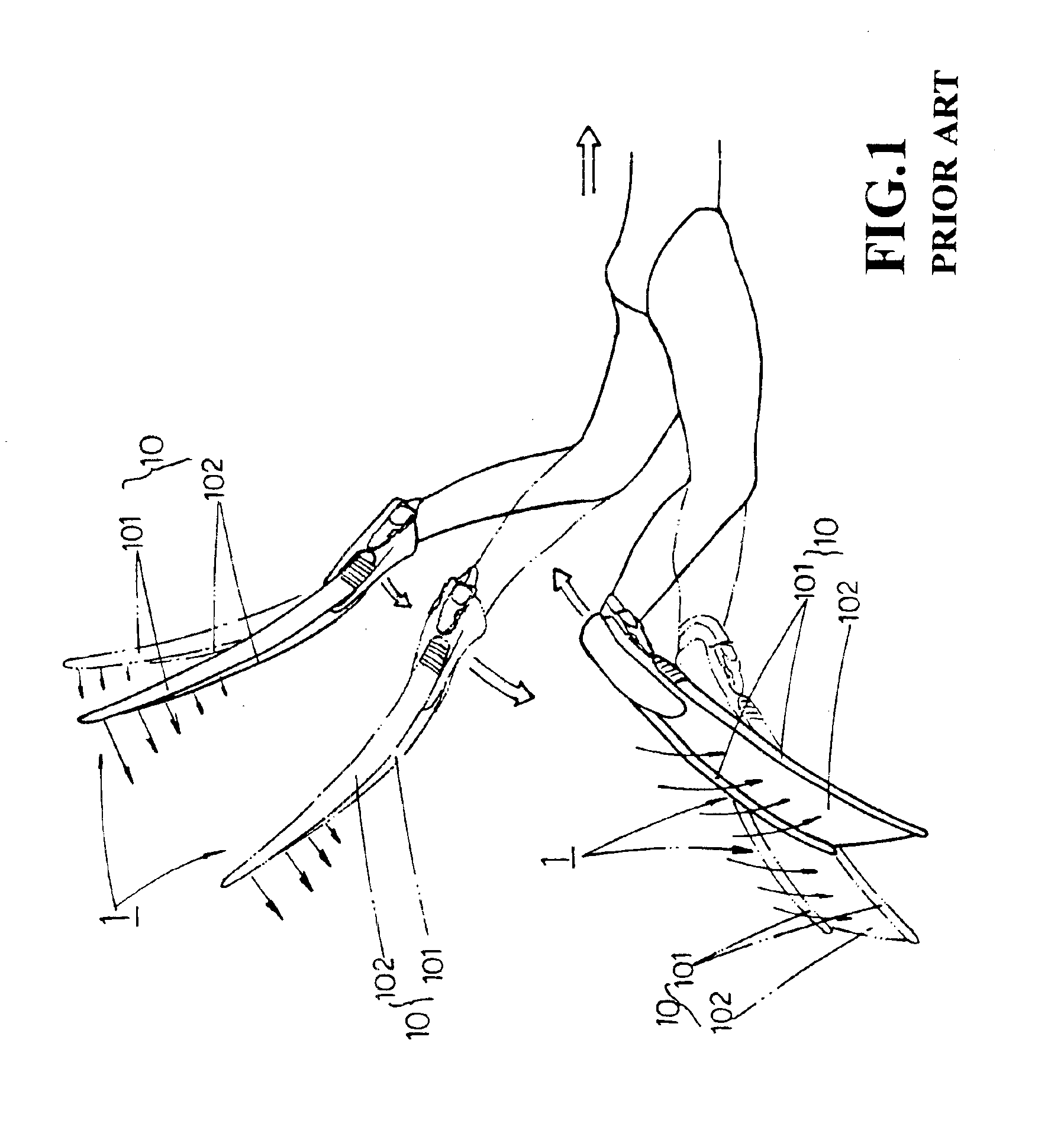
Given the oblique angle of aquatic kicking attack of the said web section 102, the reactive force (i.e., thrust) generated is not proportional to the aquatic kicking power delivered by the diver and results in less than optimal aquatic kicking efficiency.
2. As per the said shortcoming, since the fin surface 10 is in an inclined disposition, the said web surface 102 is accordingly at an oblique angle during aquatic kicking and consequently cannot provide a reactive force (thrust) that is proportional to the aquatic kicking power applied, therefore, to maintain underwater traveling speed, the diver must increase the rate of aquatic kicking, which obviously results in the drawbacks of a greater dissipation of physical strength and an easier onset of fatigue.
However, the relatively hard composition of the said longitudinal fluke 101 obviously affects the degree, of pliability of the fin surface 10, which in turn influences the degree of agility and control, resulting in stiffness and lack of smoothness.

Method used


Image

  • Diving fins
  • Diving fins
  • Diving fins

Examples


Embodiment Construction

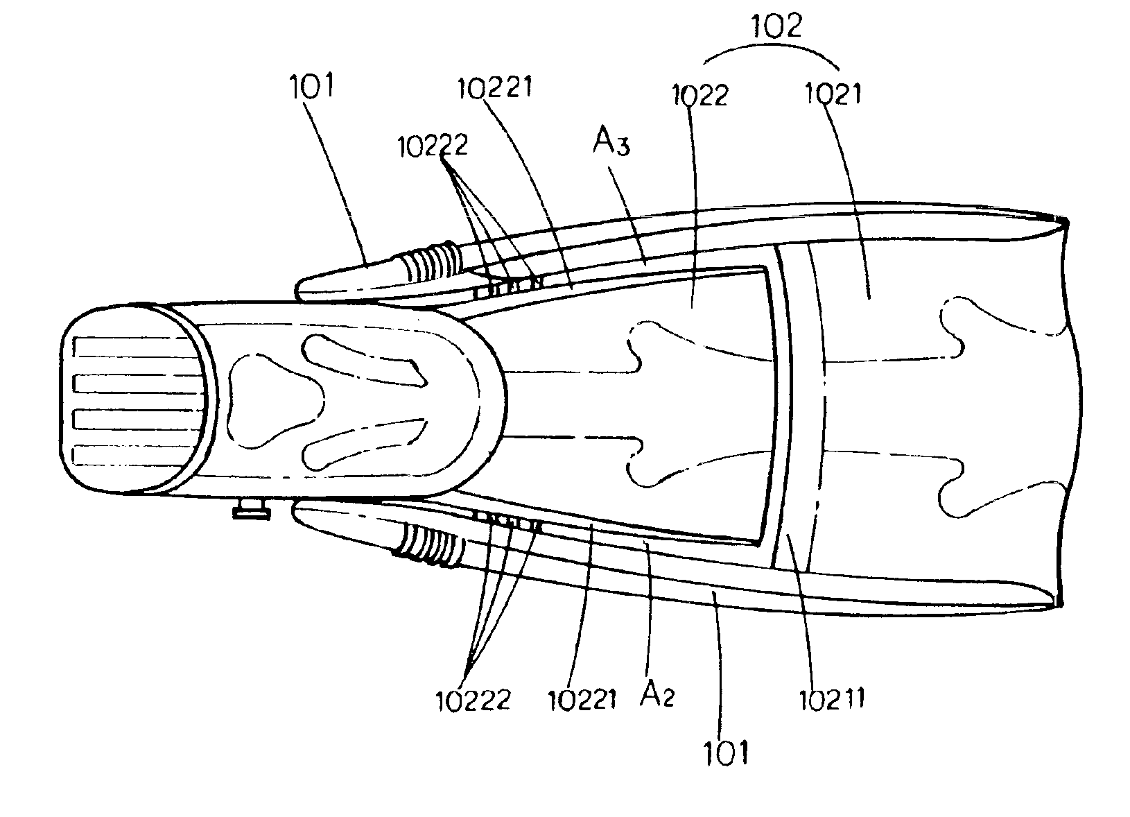
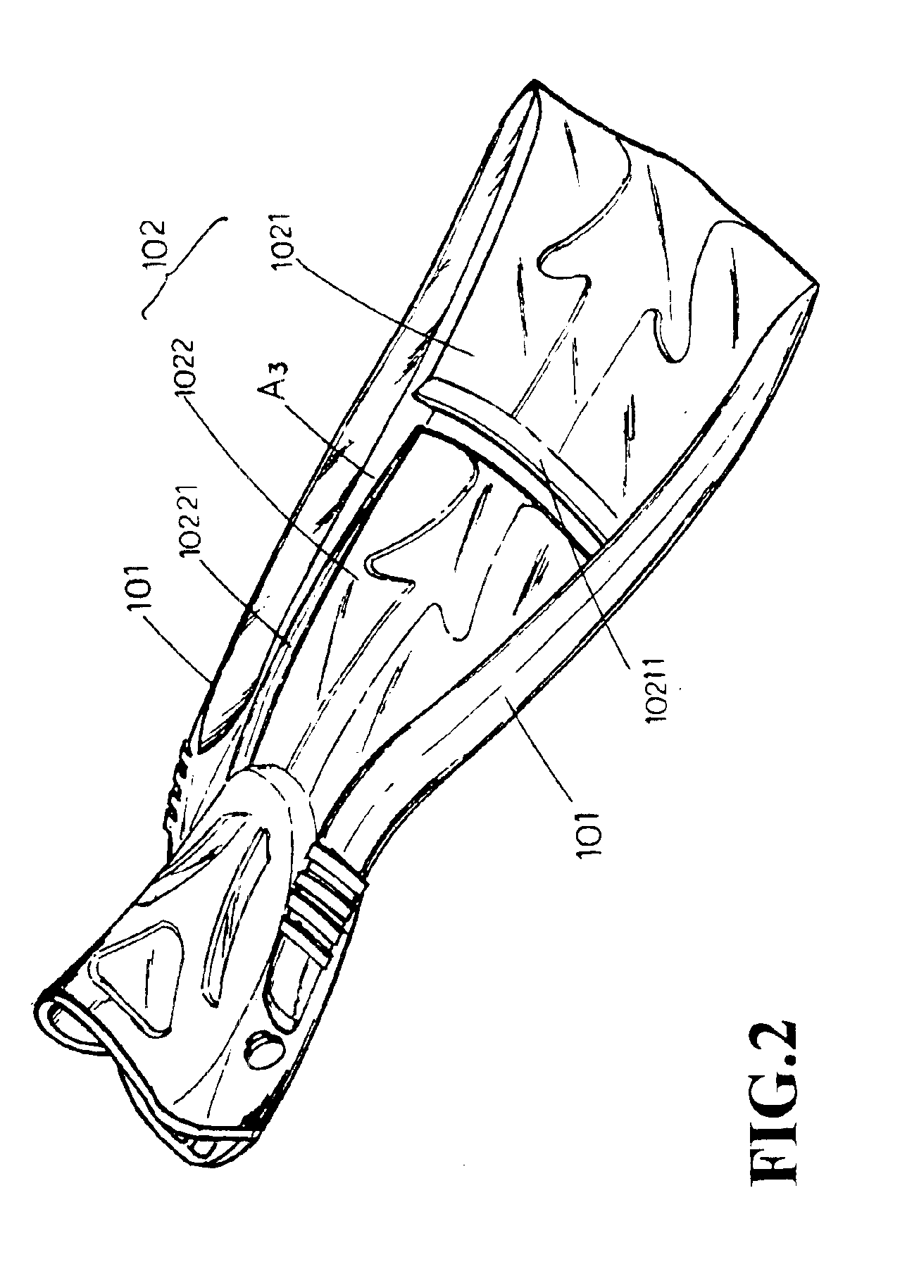
[0027]Referring to FIGS. 2, 3, and 4, it is obvious that the improved diving fins of the invention comprise a pair of tapered second longitudinal flukes 10221 respectively disposed on each longitudinal side of a second web surface 1022 (please refer to FIGS. 5 and 6); a rear end coupled to first longitudinal fluke 101 on both sides of the second longitudinal fluke 10221 and a longitudinal web section 102 being connected to a plurality of transversal adjusting flukes 10222 (please also refer to FIGS. 5 and 6) in the form of partitions; and a conical transversal fluke 10211 disposed at the rear section of the first web surface 1021 (please also refer to FIGS. 7 and 8) with its front section thinner than its rear section.

[0028]Please refer to FIGS. 9 and 10 for the present invention comprising the foregoing components. When a diver articulates both legs rearward and downward for aquatic kicking by posterior extension, due to the flexing potential of the second web surface 1022, it is a...


PUM


Abstract

An improved diving fin includes a first web surface and a second web surface. The first web surface extends between a pair of first longitudinal flukes, and the second web surface extends between a pair of tapered second longitudinal flukes. The first longitudinal flukes and the tapered second longitudinal flukes are connected at their respective rear ends. A plurality of transverse adjusting flukes are separately coupled to each of the first longitudinal flukes and the tapered second longitudinal flukes at the rear ends. Any number of the transversal adjusting flukes can be selectively severed so that a diver can change the swinging length of the second web surface according to personal needs.

Description

BACKGROUND OF THE INVENTION[0001]1) Field of the Invention[0002]The invention herein relates to improved diving fins.[0003]2) Description of the Prior Art[0004]The typical structure and operational details of a conventional pair of diving fins are shown in FIG. 1, wherein the longitudinal fin surface 10 of the said fins 1 is comprised of a single web section 102 disposed between longitudinal fluke 101 along two sides. When the diver executes the posterior extension and anterior bending of both legs (conventionally consisting of an alternating upward and downward fluttering action), the two said longitudinal flukes 101 directly support the web section 102 during the aquatic kicking sequence and enables the objective of diver mobility. Undeniably, the single web section 102 of the conventional fins that enables aquatic kicking propulsion possesses practical value and provides functional performance and, furthermore, is currently in widespread use among a majority of divers. However, t...

Claims


Application Information

Patent Timeline
Patent Type & Authority Patents(United States)
IPC IPC(8): A63B31/00A63B31/11
CPCA63B31/11
Inventor HU, CHIA-TE
Owner HU CHIA TE
Learn More