
Device for preventing refrigerant leaks in air conditioning system service ports

a technology for air conditioning systems and service ports, which is applied in the direction of refrigeration components, mechanical equipment, light and heating equipment, etc., can solve the problems that no prior art document adequately prevents refrigerant leakage in the service port of air conditioning equipmen

Active Publication Date: 2021-01-26
VIEHMEYER 45 OWNERSHIP MIKHAIL
View PDF21 Cites 0 Cited by
  • Summary
  • Abstract
  • Description
  • Claims
  • Application Information

AI Technical Summary

Benefits of technology

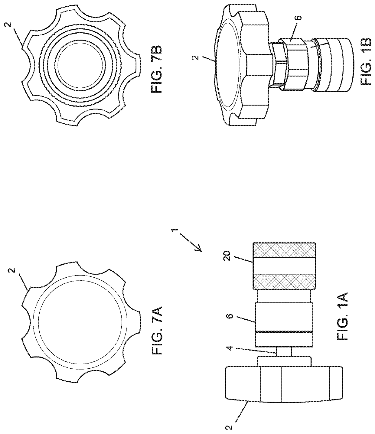
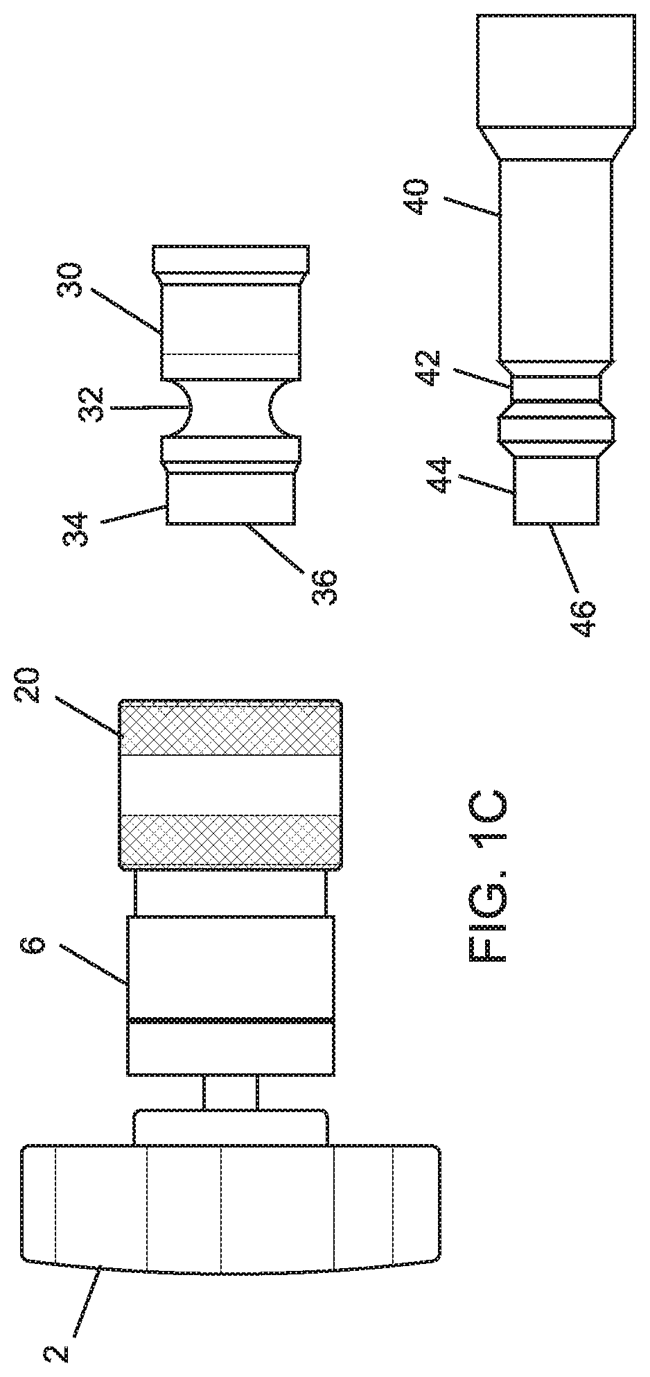
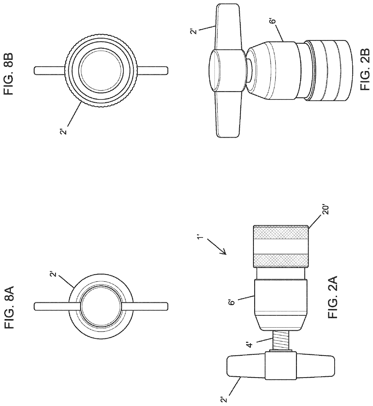
[0007]It is accordingly an object of the invention to provide a device for preventing refrigerant leaks in air conditioning system service ports, which overcomes the above-mentioned disadvantages of the heretofore-known devices of this general type and which ensures that even a refrigerant line having an aged, damaged or soiled port will be adequately sealed without the need to replace the port and thus the line.

Problems solved by technology

None of the prior art documents adequately prevent refrigerant leaks in service ports of air conditioning systems.

Method used


Image

  • Device for preventing refrigerant leaks in air conditioning system service ports
  • Device for preventing refrigerant leaks in air conditioning system service ports
  • Device for preventing refrigerant leaks in air conditioning system service ports

Examples


second embodiment

[0042]In a second embodiment shown in FIG. 6, the disk-shaped washer or pad 23 and the O-rings 15 are replaced by a rubber cup 28 which sits inside the opening 19 and receives the end 36, 46 and the extension 34, 44 of the port 30, 40. The cup may also be formed of Teflon® or nylon or any other suitable sealing material.

third embodiment

[0043]In the device shown in FIGS. 11 and 12, the handle 2 has been eliminated and the threaded shaft 4 has been replaced by a threaded shaft or Allen screw 104 provided with a recess 102 for an Allen wrench. The hollow stem 14 has been replaced by a solid stem 114. In addition, a sealing element in the form of a washer or pad 103, which may be formed of rubber, Teflon® or nylon or any other suitable sealing material, is disposed in the head 8 at the end of the spring 12. Finally, the disk-shaped washer or pad 23 has been replaced by a cup-shaped washer or pad 123 disposed in an opening 119 of the solid stem 114.

first embodiment

[0044]In order to establish an air-tight and liquid-tight seal between the washer or pad 123 and the end 36, 46 of the port 30, 40, the coupler 20 is pulled, the end 36, 46 of the port 30, 40 is inserted into the open end 26 of the main body 6 and the coupler 20 is released as in the

[0045]Then, an Allen wrench is used to rotate the threaded shaft or Allen screw 104 clockwise so that the washer or pad 103 is pushed against the end of the solid stem 114 while compressing the spring 12. The end of the screw 104 having the recess 102 will be approximately flush with the end of the head 8 when the washer or pad 103 is sufficiently tightened against a surface 115 of the solid stem 114. The port 30, 40 is locked in place by the locking balls 24 in the undercut or groove 32, 42 so that an air-tight and liquid-tight seal is established between the disk-shaped washer or pad 123 and the end 36, 46 of the port 30, 40.

[0046]In order to release the port, the threaded shaft or Allen screw 104 is t...


PUM


Abstract

A device for preventing refrigerant leaks in air conditioning system service ports includes a quick coupler for engaging the service port. A main body is disposed adjacent the coupler. A stem is movable inside the main body and a first sealing element is adjacent the stem. A head which is fastened to the main body has an internal thread and a second sealing element is disposed within the head. A shaft has an external thread to be screwed into the internal thread of the head. The shaft has an end with a recess to be engaged by a tool and the shaft has a free end remote from the recess for contacting the second sealing element, for pushing the second sealing element against the stem and for pushing the first sealing element adjacent the stem against an end of the service port upon turning the shaft.

Description

CROSS-REFERENCE TO RELATED APPLICATION[0001]This application is a Continuation-In-Part of U.S. application Ser. No. 15 / 850,991, filed Dec. 21, 2017; the prior application is herewith incorporated by reference in its entirety.BACKGROUND OF THE INVENTIONField of the Invention[0002]The invention relates to a device for preventing service ports in air conditioning systems from leaking refrigerant.[0003]The main components of an air conditioning system are a compressor, a condenser, an evaporator, an expansion valve, a dryer or accumulator and refrigerant lines interconnecting the main components. Two refrigerant lines which are attached to the compressor are metal tubes having different diameters. The smaller diameter tube is a so-called high-pressure line and the larger diameter tube is a so-called low-pressure line. Each line has a service port which is used to service the air conditioning system. The service ports are each equipped with a check valve which is intended to prevent refr...

Claims


Application Information

Patent Timeline
Patent Type & Authority Patents(United States)
IPC IPC(8): F16L55/10F16L55/115F25B41/00
CPCF16L55/1152F16L55/1157F25B41/003F25B2500/221F25B49/005
Inventor ATTIA, SHLOMO
Owner VIEHMEYER 45 OWNERSHIP MIKHAIL
Learn More