Spectral reflectometer
a spectral reflectometer and reflector technology, applied in the field of spectral reflectometers, can solve the problem of lowering the measurement accuracy of the spectrum of light detected by the light receiving portion,
- Summary
- Abstract
- Description
- Claims
- Application Information
AI Technical Summary
Benefits of technology
Problems solved by technology
Method used
Image

Examples
first embodiment
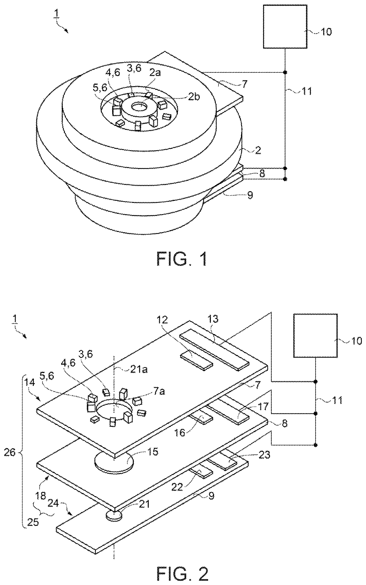
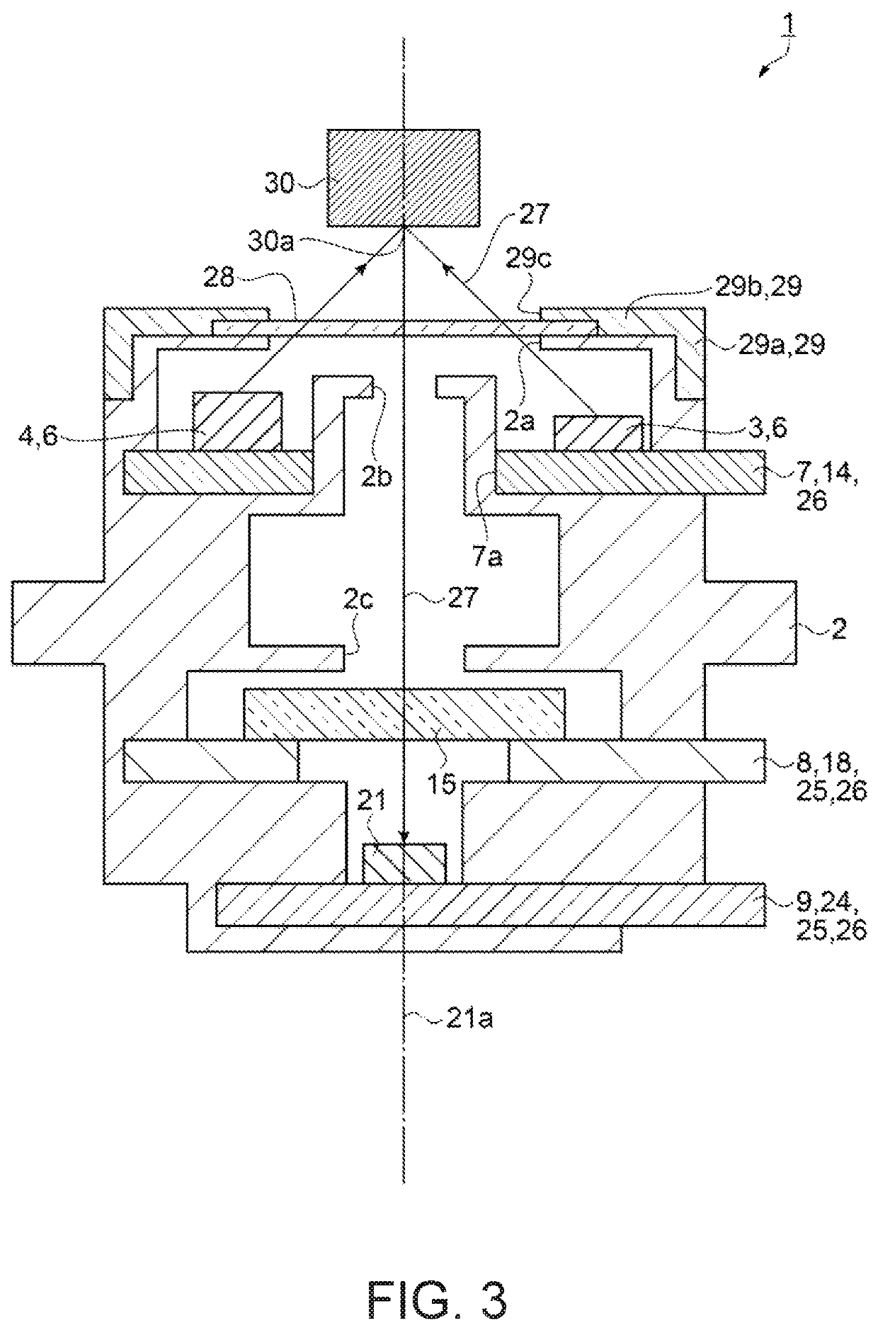
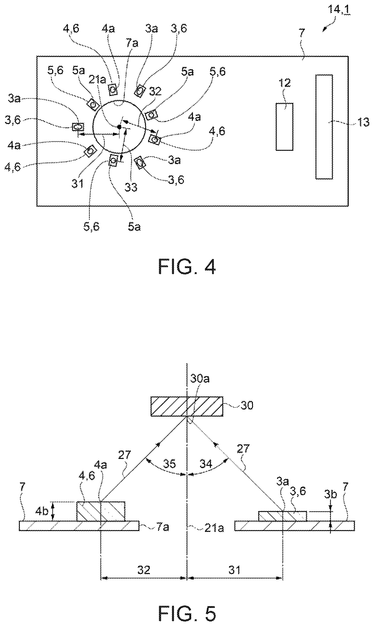
[0041]In the present embodiment, a characteristic example of the spectral reflectometer will be described with reference to drawings. A spectral reflectometer according to a first embodiment will be described with reference to FIGS. 1 to 8. FIG. 1 is a schematic perspective view showing a structure of the spectral reflectometer. As shown in FIG. 1, a spectral reflectometer 1 has a cylindrical housing 2. A first opening portion 2a is installed in the housing 2, and a first light emitting element 3, a second light emitting element 4, and a third light emitting element 5 are exposed in the first opening portion 2a. The first light emitting element 3, the second light emitting element 4, and the third light emitting element 5 are light emitting elements 6 having different external shapes. The light emitting element 6 irradiates an object to be measured with light (not shown). A second opening portion 2b is installed near the axis of the cylindrical housing 2. The spectral reflectometer ...
second embodiment
[0111]Next, an embodiment of the spectral reflectometer will be described with reference to a schematic side sectional view showing a structure of a spectral reflectometer of FIG. 9. The embodiment is different from the first embodiment in that a lens is provided between the light emitting element 6 and the observation point 30a. Descriptions of the same points as in the first embodiment will be omitted.
[0112]That is, in the embodiment, as shown in FIG. 9, the light source unit 14 is installed in a housing 64 of a spectral reflectometer 63. A lens 65 is installed at a position facing the light emitting element 6 between the light source unit 14 and the protection portion 28. The lens 65 is a convex lens. The light 27 emitted from the light emitting element 6 passes through the lens 65 and reaches the surface of the object 30 to be measured. Then, the lens 65 condenses the light 27 passing therethrough on the surface of the object 30 to be measured. Therefore, the lens 65 may efficie...
third embodiment
[0116]Next, an embodiment of the spectral reflectometer will be described with reference to FIGS. 10 to 11. FIG. 10 is a schematic side sectional view showing a structure of the spectral reflectometer. FIG. 11 is a schematic plan view showing the structure of the spectral reflectometer, in which the protection portion 28 and the support portion 29 are omitted. The embodiment is different from the first embodiment in that an opening portion is provided between the light emitting element 6 and the observation point 30a. Descriptions of the same points as in the first embodiment will be omitted.
[0117]That is, in the embodiment, as shown in FIG. 10, the light source unit 14 is installed in a housing 70 of a spectral reflectometer 69. Between the light source unit 14 and the protection portion 28, an opening portion 71 is installed between the light emitting element 6 and the object 30 to be measured on the optical axis 21a. The light 27 emitted from the light emitting element 6 passes t...
PUM
| Property | Measurement | Unit |
|---|---|---|
| angle | aaaaa | aaaaa |
| wavelength | aaaaa | aaaaa |
| peak wavelength | aaaaa | aaaaa |
Abstract
Description
Claims
Application Information