
Vascular occlusion balloon catheter

a balloon catheter and vascular occlusion technology, applied in balloon catheters, medical science, surgery, etc., can solve the problem of defective maintenance of the embolized state of the blood vessel

Active Publication Date: 2021-02-02
TERUMO CLINICAL SUPPLY
View PDF15 Cites 2 Cited by
  • Summary
  • Abstract
  • Description
  • Claims
  • Application Information

AI Technical Summary

Problems solved by technology

In addition, although the priming operation may be easily performed, the liquid injected into the balloon flows out during the use of the balloon catheters, which leads to defective maintenance of the embolized state of a blood vessel.

Method used


Image

  • Vascular occlusion balloon catheter
  • Vascular occlusion balloon catheter
  • Vascular occlusion balloon catheter

Examples


Embodiment Construction

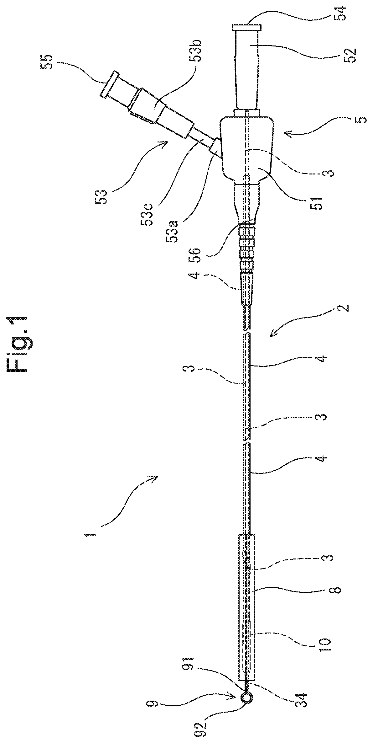
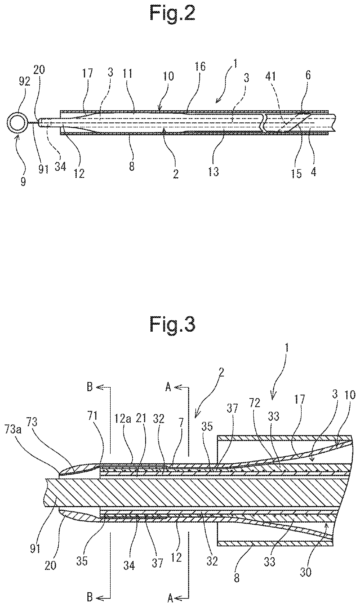
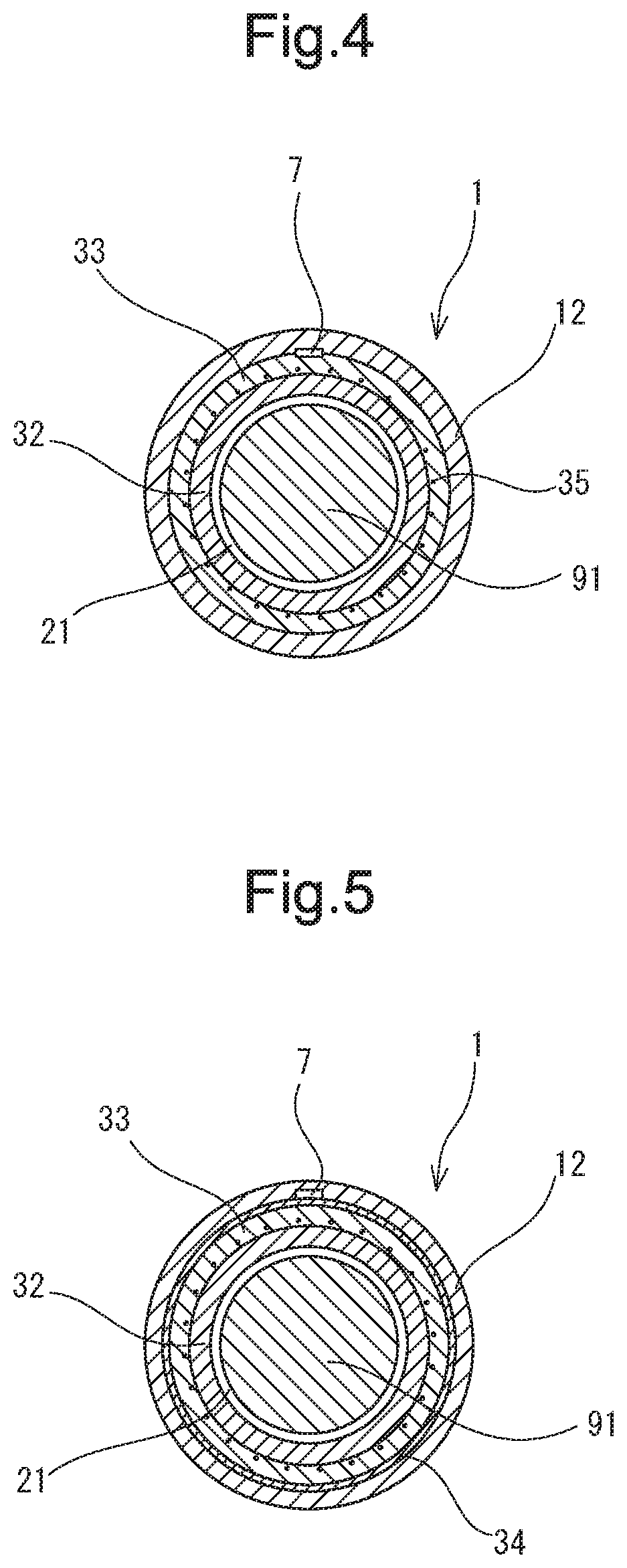
[0028]The vascular occlusion balloon catheter of the present invention is described below by using embodiments shown in the drawings.

[0029]A vascular occlusion balloon catheter (hereinafter referred to as balloon catheter) 2 of the present invention has a vascular occlusion balloon (hereinafter referred to as balloon) 10 elastically deformable and a shaft part having a main lumen 21 and a balloon expanding lumen 22. The vascular occlusion balloon catheter 2 has an air discharge passage 7. The air discharge passage 7 has a distal end (distal end opening 71) located at a position distal from the balloon 10 of the balloon catheter 2 and a proximal end communicates with an inner portion of the balloon 10. The distal end opening 71 of the air discharge passage 7 is positioned inside a portion disposed proximally from the distal end of the balloon catheter 2. As described above, the air discharge passage 7 communicates with the main lumen 21 at its distal end opening 71. The area of a cro...


PUM


Abstract

The vascular occlusion balloon catheter has a balloon, a main lumen, and a balloon expanding lumen. The balloon catheter has an air discharge passage. The air discharge passage has a distal end opening located at a position distal from the balloon and a proximal end communicating with an inner portion of the balloon. The distal end opening of the air discharge passage is positioned inside a portion disposed proximally from a distal end of the balloon catheter. The air discharge passage communicates with the main lumen at the distal end opening of the air discharge passage. The area of a cross section of the air discharge passage orthogonal to an axial direction of the balloon catheter is set to 200 μm2 to 450 μm2. The length of the air discharge passage is set to 1.0 to 3.0 mm.

Description

BACKGROUND OF THE INVENTION[0001]Field of the Invention[0002]The present invention relates to a vascular occlusion balloon catheter to be inserted into a blood vessel.[0003]Description of the Related Art[0004]The vascular occlusion balloon catheter is used to perform angiography, inject a liquid medicine such as a chemotherapeutic agent into blood vessel, and perform vascular embolization.[0005]The balloon catheter disclosed in U.S. Pat. No. 4,638,805 [Japanese Examined Patent Application Publication No. 03(1991)-56067] (Patent document 1) has the apparatus for discharging air from the inside of the balloon and restraining the liquid from escaping from the balloon. As the apparatus for discharging the air from the inside of the balloon and restraining the liquid from escaping from the balloon, there is disclosed the very small passage 21 extended from the inside of the balloon to the periphery of the distal end of the balloon catheter 11. According to the disclosure, the wire used t...

Claims


Application Information

Patent Timeline
Patent Type & Authority Patents(United States)
IPC IPC(8): A61M25/10A61B17/12A61M25/01A61M5/36A61M25/00
CPCA61M25/10A61B17/1204A61B17/12109A61B17/12136A61M5/36A61M25/0102A61M25/104A61M25/005A61M25/1006A61M2025/1052A61M2025/1077A61M2025/1079A61M2025/1081
Inventor GOTO, KAZUMIKAWASE, TATSUYANAKANISHI, NOZOMIHIROSE, SAYUMI
Owner TERUMO CLINICAL SUPPLY
Learn More