Surgical wire driver capable of automatically adjusting for the diameter of the wire or pin being driven

a wire or pin diameter technology, applied in the field of wire drivers, can solve the problems of limiting the axial load to which the implant can be exposed, the likelihood of the wire or pin buckle, and the axial load to which the wire or pin is exposed, and achieves significant differences in the diameter

Active Publication Date: 2021-02-23
STRYKER CORP
View PDF16 Cites 1 Cited by
  • Summary
  • Abstract
  • Description
  • Claims
  • Application Information

AI Technical Summary

Problems solved by technology

Owing to the relatively small cross sectional size of the wire or pin, there is a limit to the axial load to which the implant can be exposed before the implant will buckle or bend.
This limits the axial load to which the wire or pin is exposed and the likelihood that the wire or pin will buckle.
This results in a design challenge because the diameter of these implants are, proportionally, very different.
The design challenge is present because this lever is typically located in front of the grip integral with the handpiece with which the wire drive is associated.
A problem arises because some surgeons, particularly surgeons with small hands, find it difficult to, with a single hand grip both the handgrip and the lever and pivot the lever.
This problem is exasperated when a wire or pin having a relatively large diameter is fitted to the same wire driver.
When the lever is so located relative to the grip, it can become even more difficult for the surgeon to grasp the lever in order to grasp the wire or pin in place so the wire or pin can be driven into bone.
A disadvantage of the above solution is that this requires the personnel in the operating room, prior to the use of the wire driver, set the lever to the appropriate position as a function of the diameter of the wire or pin.
If the lever is not properly set at a minimum, it may be ergonomically difficult for the surgeon.
In a more serious scenario the wire driver may not be able to drive the wire or pin until the lever is properly set.
If a surgeon needs to apply a significant amount of force to drive plural pins or wires into a patient, the need to perform this activity over an extended period of time can fatigue the surgeon.

Method used


Image

  • Surgical wire driver capable of automatically adjusting for the diameter of the wire or pin being driven
  • Surgical wire driver capable of automatically adjusting for the diameter of the wire or pin being driven
  • Surgical wire driver capable of automatically adjusting for the diameter of the wire or pin being driven

Examples


first embodiment

I. First Embodiment

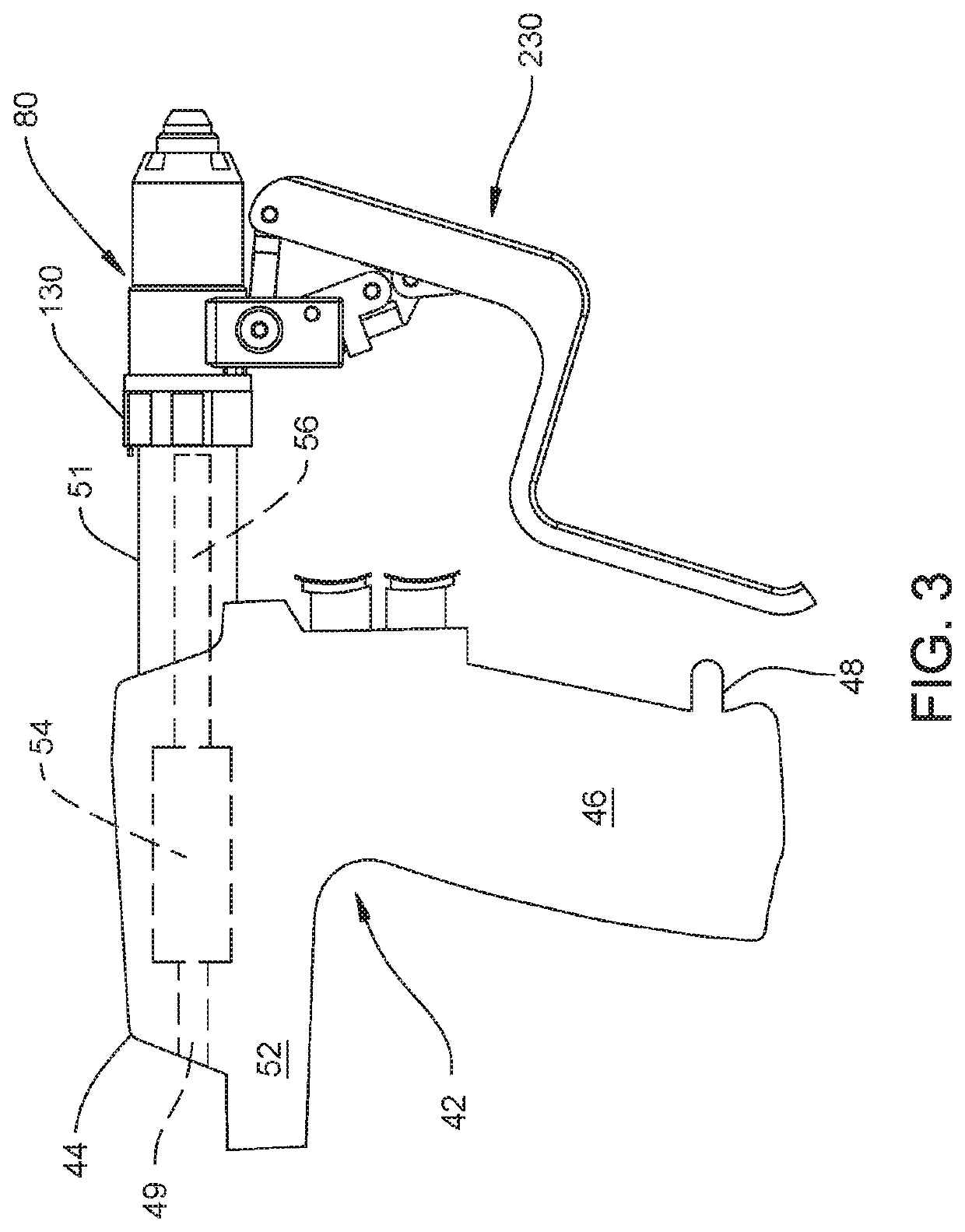
[0078]FIGS. 3 and 4 provide an overview of the wire driver of this invention. In the depicted version of the invention, the wire driver consists of a handpiece 42 to which a wire driver attachment 80 is removably attached. Handpiece 42 includes a housing or shell that forms the body 44 of the handpiece. The depicted handpiece 42 is pistol shaped. The body 44 includes a handgrip 46. A finger 48 extends distally forward from the distally directed surface of the handgrip 46. (Here “distal” is understood to mean away from the practitioner holding the handpiece, towards the site at which the wire or pin is to be driven into patient. “Proximal” is understood to mean towards the practitioner holding the handpiece, away from the site at which the wire or pin is to be fitted.) A barrel 52 is located above the handgrip 46. The barrel 52 extends both distally forward from and proximally away from the handgrip 46. A head 51 extends distally forward from the barrel. While not ...

first alternative embodiment

II. First Alternative Embodiment

[0157]FIGS. 37 and 387 depict an alternative wire driver 560 of this invention. Wire driver 560 has some of the same basic components of previously described wire driver 80. To avoid redundancy, the majority of these identical components are neither described not illustrated.

[0158]Wire driver 560 includes a lever assembly 562 different from lever assembly 270. Lever assembly 562 includes the previously described actuator link 306. Actuator link 306 is mounted to the legs 92 integral with housing 84 as described with respect to wire driver 80. A lever 564 pivots actuator link 306. Lever 564, like lever 232, has a top section that extends generally vertically downwardly from the housing 84 and middle section that extends perpendicularly and proximally away from the top section. Lever 564 also has a bottom section that extends perpendicularly downwardly from the middle section. The individual sections of lever 564 are not identified. Two parallel and spa...

second alternative embodiment

III. Second Alternative Embodiment

[0164]A second alternative wire driver 602 is now described by initial reference to FIGS. 39 and 40. Wire driver 602 includes the same basic internal components as wire drivers 80 and 560. Accordingly, these basic components are not redescribed.

[0165]Wire driver 602 includes a lever assembly 604. Lever assembly 604 includes a lever 606. Lever 606 includes a head 608. The lever head 608 includes two spaced apart parallel ears 610. Each ear 610 is formed with two through holes. A first through hole, hole 611, is located adjacent the top of each ear 610. A second through hole, hole 612, is located further from the tip. The ears extend downwardly to a base 613 also part of the head. A bent metal beam 614, also part of the lever 606, extends downwardly from head base 613. The beam 614 is shaped to immediately below the head, curve downwardly and proximally. The beam 614 then extends proximally so as to have a section that is generally parallel with the l...


PUM


Abstract

A wire driver for driving a wire or pin into living tissue. A plural bar linkage that includes a lever is actuated to drive the components that selectively grasp the wire from a release state to a grasping state.

Description

FIELD OF THE INVENTION[0001]This invention relates generally to a wire driver used to drive a wire or a pin into a patient. The driver of this invention is able to drive the wire or pin into the patient with minimal, if any, adjustment due to the diameter of the wire or pin.BACKGROUND OF THE INVENTION[0002]A wire driver is a type of motorized surgical tool. Generally, a motorized surgical tool includes a handpiece in which a motor is housed. A wire driver is includes a grasping mechanism that holds either a wire or a pin so that the wire or pin rotates upon actuation of the motor. The wire or pin is rotated so the wire or pin can be driven into tissue, typically bone. It is desirable so drive a wire or a pin into a bone to stabilize a fracture or a break in the bone. Both wires and pins are driven into a patient for this purpose. Alternatively, it may desirable to insert a pin into a patient to secure some sort of other implant, such as plate, to the bone.[0003]A wire or a pin is an...

Claims


Application Information

Patent Timeline
Patent Type & Authority Patents(United States)
IPC IPC(8): A61B17/88A61B17/16A61B34/00A61B17/00
CPCA61B17/8897A61B17/1697A61B34/71A61B2017/00318A61B2017/00477
Inventor XIE, MARK M.CHILDERS, ROBERT W.
Owner STRYKER CORP
Why Eureka
Try Eureka