Conveyor belt sterilization apparatus and method

a conveyor belt and apparatus technology, applied in the field of conveyor belt sterilization apparatus and method, can solve the problems of interrupting the clerk's work flow and being messy

Active Publication Date: 2021-03-02
KLENLITE LLC
View PDF27 Cites 1 Cited by
  • Summary
  • Abstract
  • Description
  • Claims
  • Application Information

AI Technical Summary

Problems solved by technology

Clerks at the grocery store can use sanitary wipes or spray cleaning fluids with disinfectants onto the conveyors, but such activities interrupt the clerk's work flow and can be messy.

Method used


Image

  • Conveyor belt sterilization apparatus and method
  • Conveyor belt sterilization apparatus and method
  • Conveyor belt sterilization apparatus and method

Examples


Embodiment Construction

is hereafter described with specific reference being made to the drawings in which:

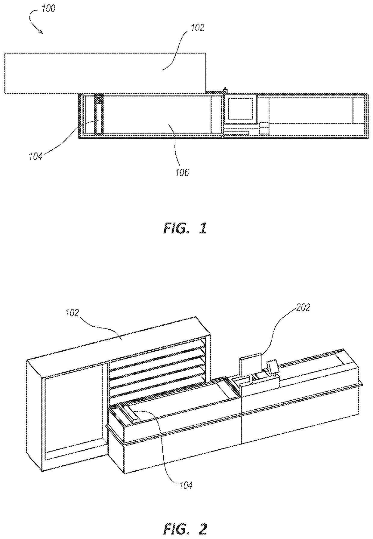
[0025]FIG. 1 shows a top perspective view illustrating one aspect of a conveyor belt sterilization system;

[0026]FIG. 2 is a perspective view illustrating one aspect of a conveyor belt sterilization system;

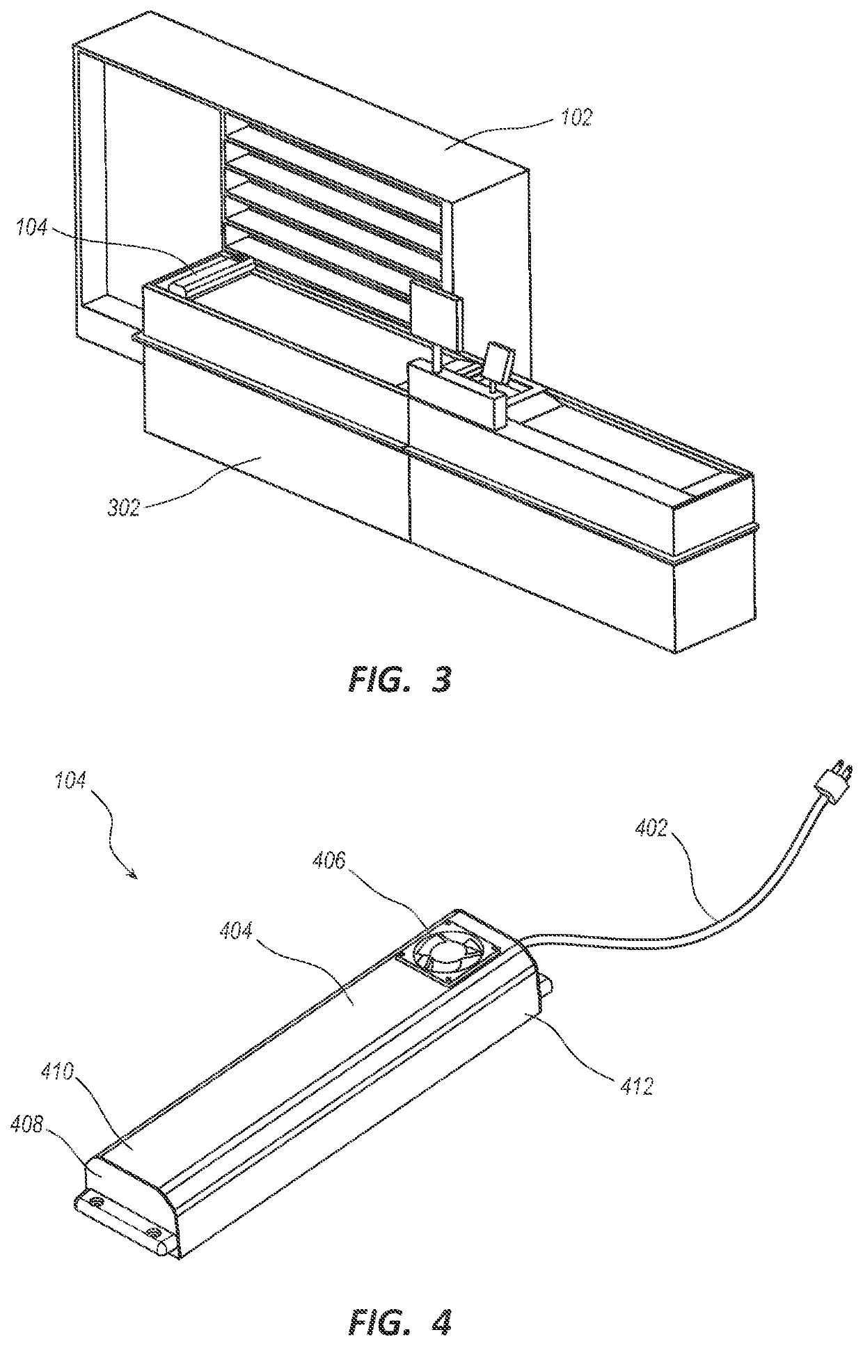
[0027]FIG. 3 is a side perspective view illustrating one aspect of a conveyor belt sterilization system;

[0028]FIG. 4 is a perspective view illustrating one aspect of the conveyor belt sanitization apparatus;

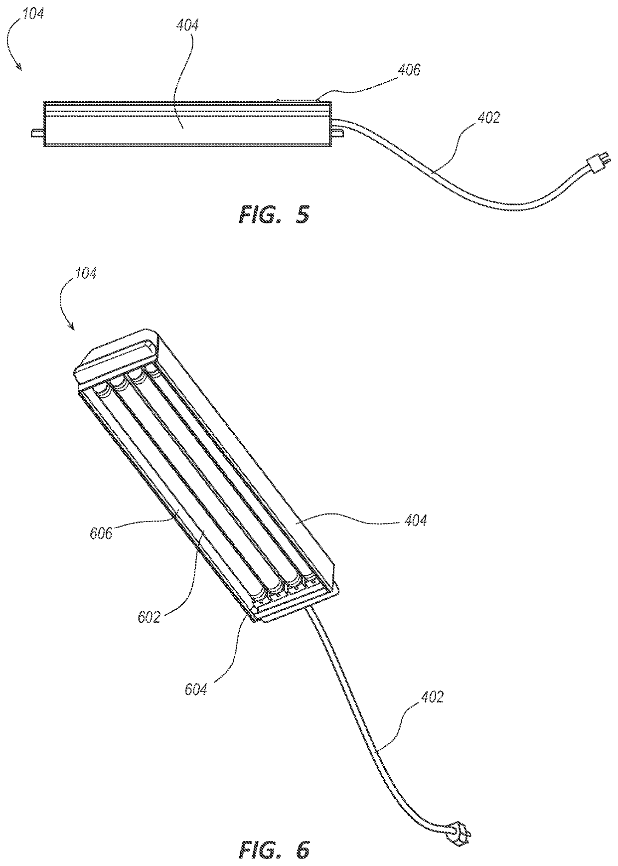
[0029]FIG. 5 is a perspective view illustrating one aspect of the conveyor belt sanitization apparatus;

[0030]FIG. 6 is a lower perspective view illustrating one aspect of the conveyor belt sanitization apparatus;

[0031]FIG. 7 is a perspective view illustrating one aspect of the conveyor belt sanitization apparatus;

[0032]FIG. 8 is an exploded view of the conveyor belt sanitization apparatus; and

[0033]FIG. 9 is a flow chart illustrating one method of sterilizing a conveyor belt.

DETAILED DESCRIPTION

[0...


PUM

PropertyMeasurementUnit
movementaaaaaaaaaa
distanceaaaaaaaaaa
poweraaaaaaaaaa

Abstract

A conveyor belt sanitization apparatus and method are provided for sanitizing a conveyor belt of the species commonly found at grocery stores and supermarkets using ultraviolet (UV) light. One or more UV light bulbs in the apparatus may be positioned to effectively sanitize a conveyor belt.

Description

RELATED APPLICATIONS[0001]This application is a U.S. non-provisional application, which claims priority under 35 U.S.C. 120 and 119(e) to U.S. provisional application No. 63 / 013,486, filed Apr. 21, 2020 and to U.S. provisional application No. 62 / 706,213, filed Aug. 5, 2020. The disclosure of these priority applications are incorporated herein in their entirety, by this reference.BACKGROUND1. Field of the Invention[0002]This invention relates to sterilizing surfaces, and more particularly relates to an apparatus and method of sterilizing a conveyor belt.2. Description of the Related Art[0003]Viral outbreaks of SARS-CoV-2, SARS, Ebola, MERS, and H1N1 have increased the public's awareness of contaminated surfaces. Commonly-shared hard surfaces may collect a contagion, such as a virus, and facilitate transmittal of the contagion from one carrier to others.[0004]Examples of commonly shared surfaces include gas pump handles, door handles, and conveyor belts such as those found in consumer...

Claims


Application Information

Patent Timeline
Patent Type & Authority Patents(United States)
IPC IPC(8): A61L2/10B65G45/10A47F9/04
CPCA61L2/10B65G45/10A47F9/04A47F2009/041A61L2202/11A61L2202/14B65G2203/0266B65G2203/044
Inventor ROBINSON, SCOTT DAVIDBROWN, JEREMIAH DEAN
Owner KLENLITE LLC
Why Eureka
Try Eureka