
Stator unit, stator, and motor comprising same

a stator and stator technology, applied in the direction of windings, dynamo-electric components, magnetic circuit shapes/forms/constructions, etc., can solve the problems of core stack reduction, mass productivity decline, performance degradation, etc., to reduce the size of the bus bar, improve mass productivity, and reduce the effect of stack reduction

Active Publication Date: 2021-03-16
LG INNOTEK CO LTD
View PDF23 Cites 0 Cited by
  • Summary
  • Abstract
  • Description
  • Claims
  • Application Information

AI Technical Summary

Benefits of technology

[0032]A stator unit, a stator, and a motor including the same according to an embodiment having the above-described configuration can implement serial winding using a coil around a unit stator core, on which three teeth are provided, thereby improving mass productivity.
[0033]Further, since a serial circuit is implemented by winding, performance degradation according to stack reduction can be prevented. Accordingly, a size of a bus bar can be minimized.
[0034]In addition, when the coil is wound around each unit stator core on which three teeth are provided, individual winding according to application of the unit stator core can be applied. Accordingly, since minimization of a winding time and maintenance of a winding apparatus are easy, investment cost can be minimized.
[0035]In addition, since the unit stator core on which three teeth are provided is used, a horizontal tolerance between unit stator cores is minimized and an evenness degree can be managed. Accordingly, performance degradation and a cause of a noise and vibration occurrence can be minimized. Accordingly, reliability of the motor can be improved.

Problems solved by technology

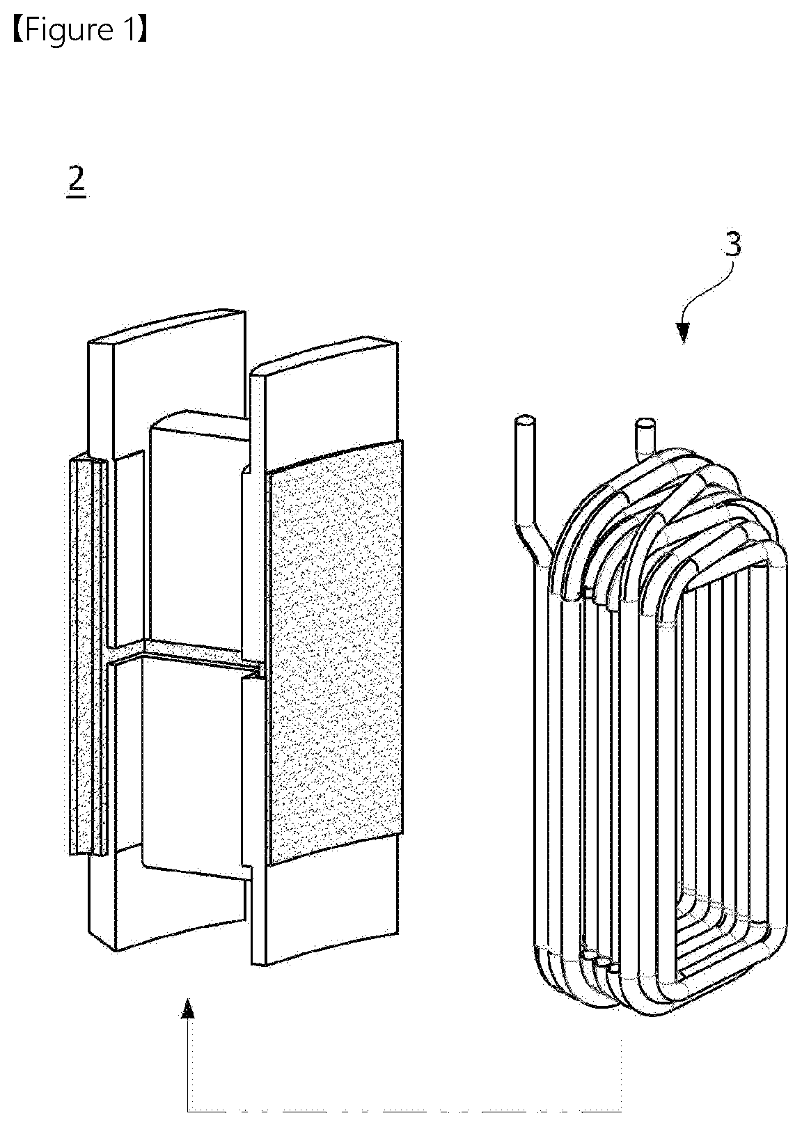
Accordingly, when a coil 3 is wound, since a serial circuit is difficult to be implemented in equipment, mass productivity decreases.
Further, when a bus bar is used to implement the serial circuit, core stack decreases and the performance is degraded.
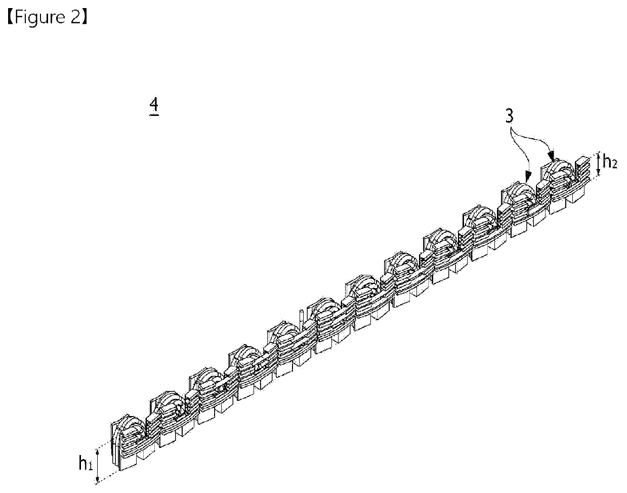
Meanwhile, in a case of an unfolding core 4 shown in FIG. 2, since three nozzle winding cannot be implemented due to a characteristic of the unfolding core, investment cost increases.

Method used


Image

  • Stator unit, stator, and motor comprising same
  • Stator unit, stator, and motor comprising same
  • Stator unit, stator, and motor comprising same

Examples


Embodiment Construction

[0046]Since the present invention may be variously changed and have various embodiments, particular embodiments will be exemplified in the drawings and described. However, the present invention is not limited to the particular embodiment and includes all changes, equivalents, and substitutes falling within the spirit and the scope of the present invention.

[0047]Further, it should be understood that, although the terms “first,”“second,” and the like may be used herein to describe various elements, the elements are not limited by the terms. The terms are only used to distinguish one element from another. For example, a first element could be termed a second element, and similarly, a second element could be termed a first element without departing from the scope of the present invention. The term “and / or” includes combinations of one or all of a plurality of associated listed items.

[0048]When predetermined components are mentioned to be “linked,”“coupled,” or “connected” to other compo...


PUM


Abstract

Embodiments relate to a stator unit, a stator, and a motor comprising same, the stator unit comprising: a unit stator core; an insulator disposed on the unit stator core; and a coil wound on the insulator, wherein the unit stator core comprises a main body formed so as to have a prescribed curvature with reference to the centre, and three teeth formed so as to protrude toward the centre from the main body, the main body comprising notches formed between the teeth. Thus mass productivity can be increased as a result of series winding using a coil on a unit stator core having three teeth arranged thereon.

Description

Cross Reference to Related Applications[0001]This application is the National Phase of PCT International Application No. PCT / KR2017 / 006704, filed on Jun. 26, 2017, which claims priority under 35 U.S.C. 119(a) to Patent Application No. 10-2016-0086216, filed in the Republic of Korea on Jul. 7, 2016, all of which are hereby expressly incorporated by reference into the present application.TECHNICAL FIELD[0002]The present invention relates to a stator unit, a stator, and a motor including the same.BACKGROUND ART[0003]A motor is an apparatus configured to convert electrical energy to rotation energy using a force that a conductor receives in a magnetic field. Recently, since purposes of a motor are increasing, a function of the motor has become important. Particularly, since electrification of a vehicle is rapidly proceeding, demands for a motor applied to a steering system, a braking system, a designing system, and the like are significantly increasing.[0004]Generally, the motor is prov...

Claims


Application Information

Patent Timeline
Patent Type & Authority Patents(United States)
IPC IPC(8): H02K1/14H02K3/32H02K3/52H02K5/22H02K3/34
CPCH02K3/325H02K1/14H02K1/148H02K3/34H02K3/52H02K3/522H02K5/22H02K2203/09H02K3/28H02K2203/12H02K3/521H02K3/345
Inventor AN, IL HWAN
Owner LG INNOTEK CO LTD
Learn More