
Forecarriage of a rolling motor vehicle with rolling block

a technology of rolling motor vehicles and rolling blocks, which is applied in the direction of vehicles, cycles, transportation and packaging, etc., can solve the problems of reducing the overall dimensions of the system, reducing the overall cost of the system, and limiting the use of power actuators, so as to reduce the overall cost and increase the overall cost. the effect of the system and the overall cos

Active Publication Date: 2021-03-23
PIAGGIO & C SPA
View PDF17 Cites 0 Cited by
  • Summary
  • Abstract
  • Description
  • Claims
  • Application Information

AI Technical Summary

Benefits of technology

The present invention provides a forecarriage of a rolling motor vehicle with an anti-roll system that can be installed easily and at a low cost. The system uses a smaller actuator than previous designs, and is effective in blocking rolls in a non-abrupt manner. The system can also be symmetrically installed on both wheels without increasing the overall size or cost. The technical effects of the invention include a simpler and more cost-effective design to prevent roll-related issues in rolling motor vehicles.

Problems solved by technology

Due to the structural features of this type of vehicles, it is possible that under certain conditions, for example at very low speeds or during stops, the motor vehicle may fall as a result of an accidental and / or uncontrolled roll movement.
Such a technical solution, however, has the limit of requiring the use of power actuators, having a size sufficient to provide sufficient torque not only to maintain balance in the motor vehicle by blocking the rolling movements thereof, but also to prevent such a balance from being modified by moving all the weight of the motor vehicle on one side.
This technical solution, however, requires more complicated installation and does not allow significantly reducing the problem of the overall dimensions.

Method used


Image

  • Forecarriage of a rolling motor vehicle with rolling block
  • Forecarriage of a rolling motor vehicle with rolling block
  • Forecarriage of a rolling motor vehicle with rolling block

Examples


Embodiment Construction

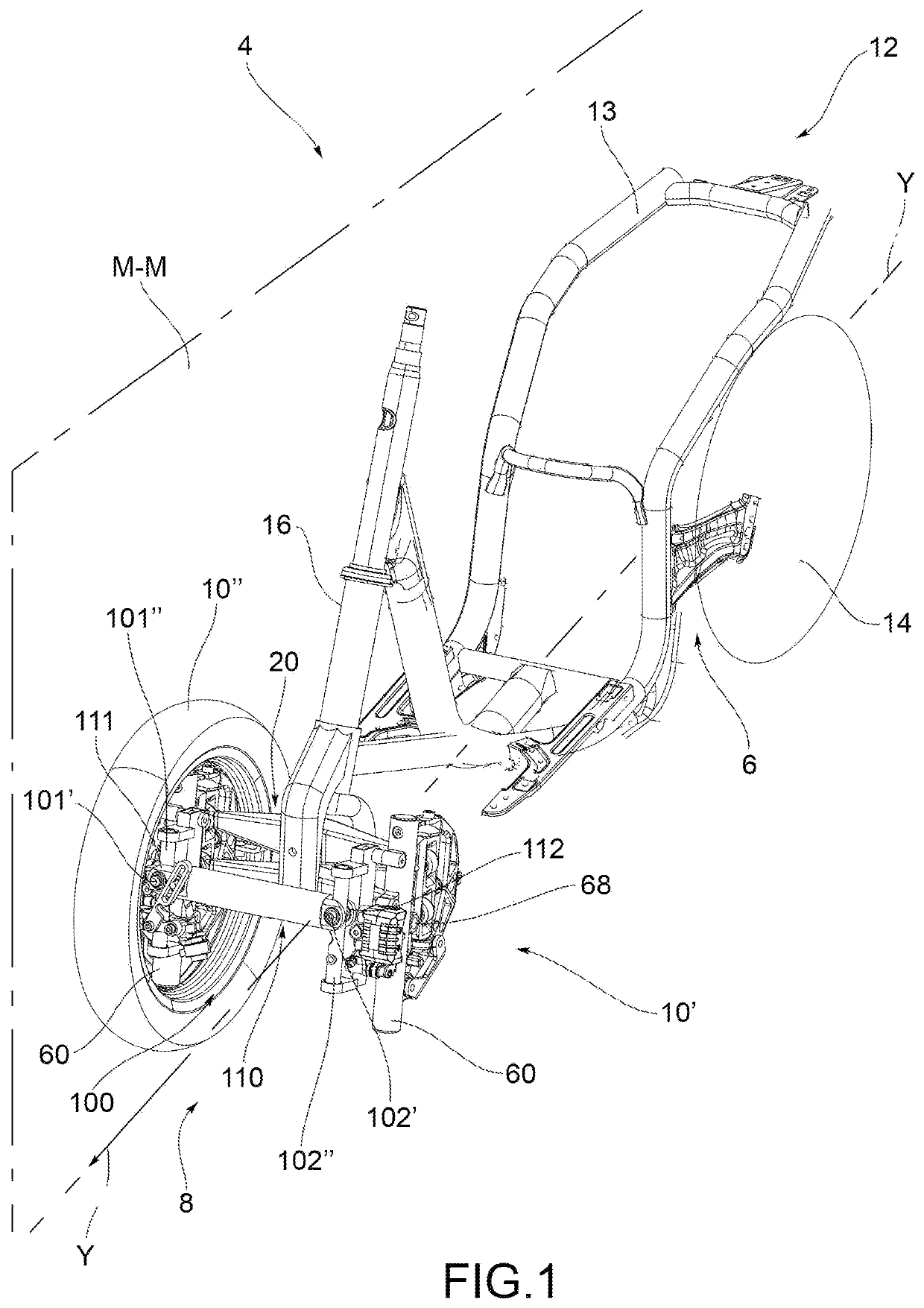
[0037]With reference to the above figures, reference numeral 4 globally denotes a motor vehicle according to the present invention.

[0038]For the purposes of this invention, it should be noted that the term motor vehicle must be considered in a broad sense, encompassing any motor vehicle having at least three wheels, i.e. two front wheels, as better described below, and at least one rear wheel. Therefore, the definition of motor vehicle also encompasses the so-called quads, with two wheels at the forecarriage and two wheels at the rear.

[0039]The motor vehicle 4 comprises a frame 6 extending from a forecarriage 8 supporting at least two front wheels 10, to a rear 12 supporting one or more rear wheels 14. It is possible to distinguish a left front wheel 10′ and a right front wheel 10″, wherein the definition of left and right wheel 10′, 10″ is purely formal and means in relation to a driver of the vehicle. Said wheels are arranged to the left and right of a centre line M-M of the motor...


PUM


Abstract

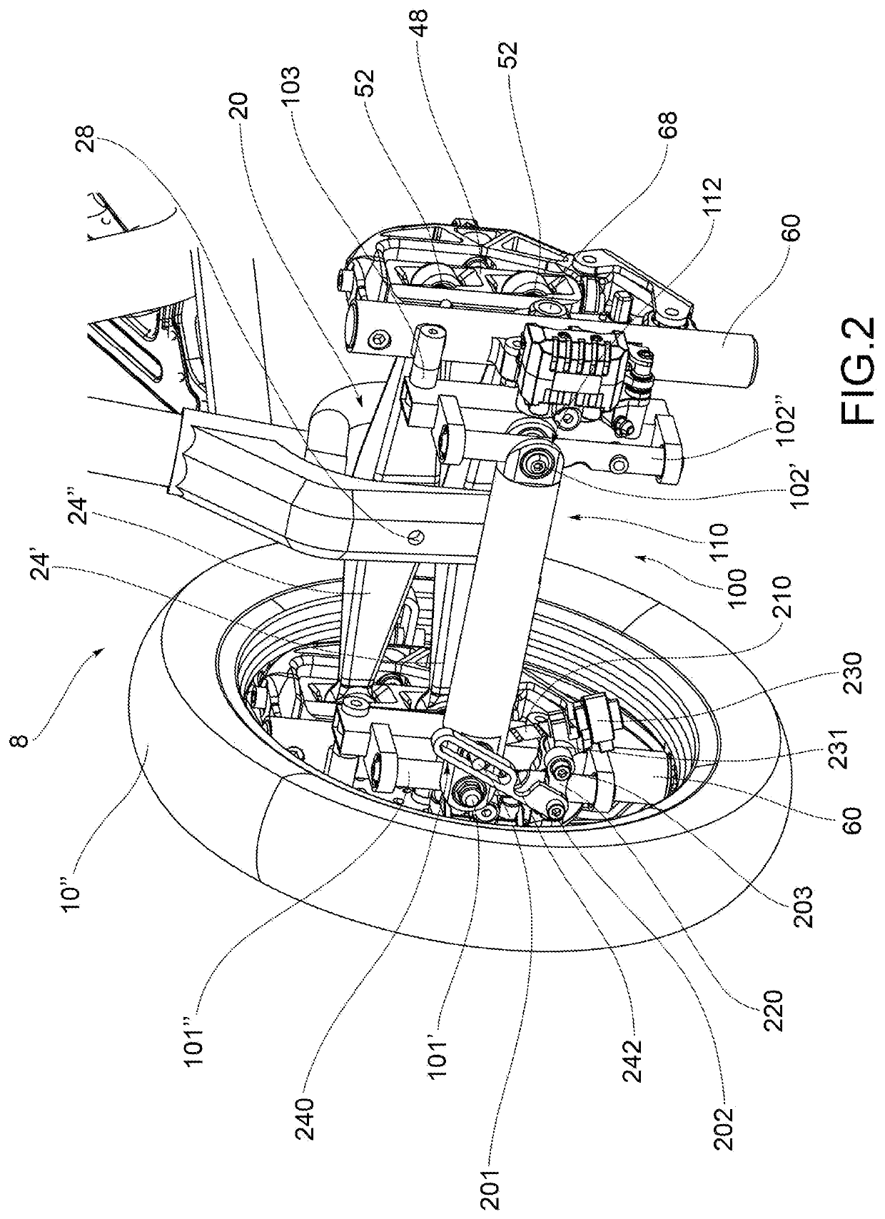
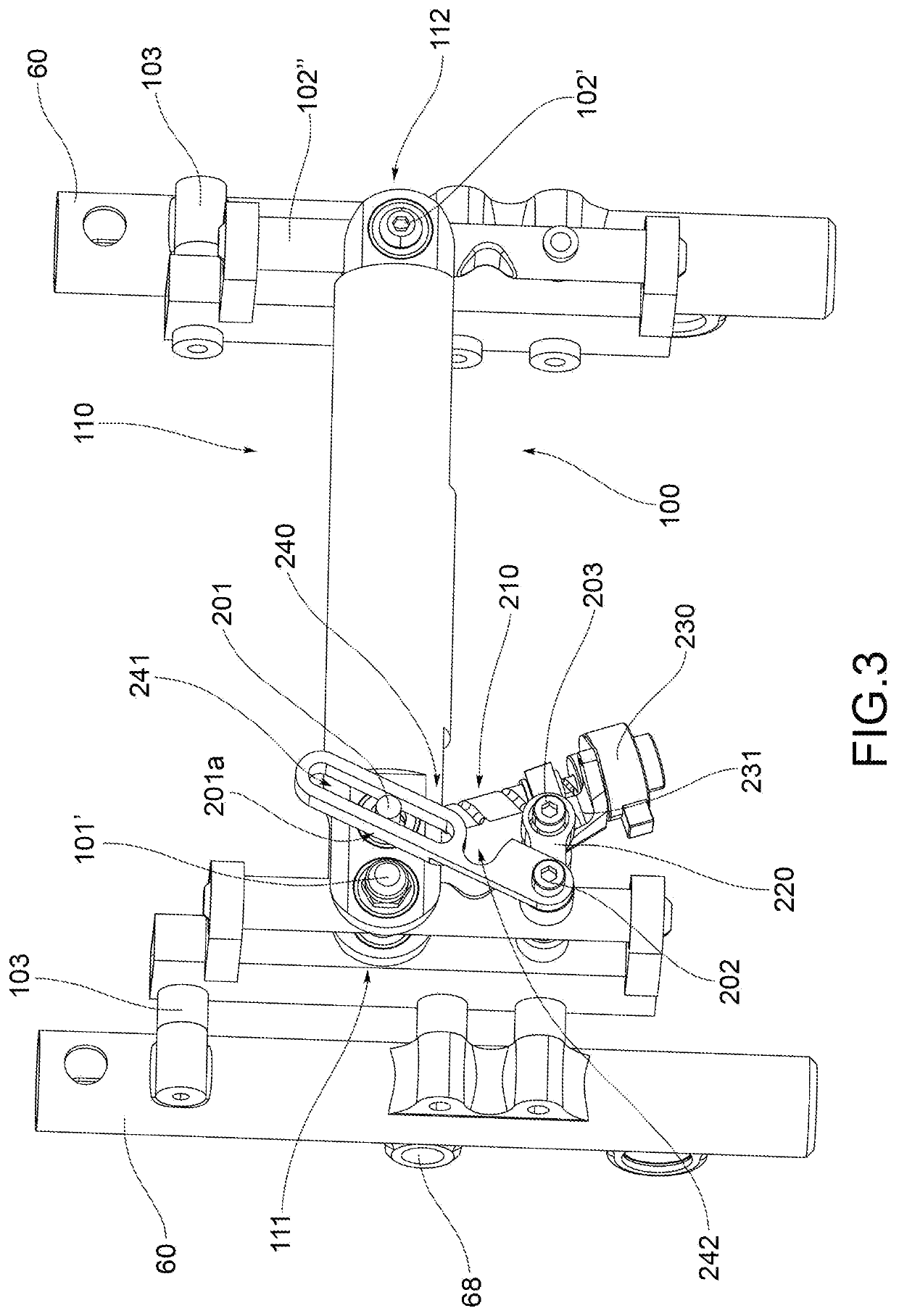
The present invention relates to a forecarriage of a rolling motor vehicle with three or four wheels, comprising: a forecarriage frame (16); at least one pair of front wheels (10′), (10″) kinematically connected to each other and to the forecarriage frame by a kinematic roll mechanism (20) which enables the same to roll in a synchronous and specular manner; an anti-roll system (100) comprising a rod (110) having a first (111) and a second end (112) opposite each other which connect by means of hinging means (101′, 101″; 102′, 102″) a first (60) and a second anchoring portion (60) of forecarriage 8 directly to each other. At least one of said first and second anchoring portions is subject to roll movements of said two front wheels. The hinging means are configured to passively follow the movements of the two anchoring portions. The hinging means (101′, 101″) at the first end of the rod comprise at least a first roll hinge (101′) which has its hinge axis substantially orthogonal to a rolling plane of the two front wheels and is connected to the first anchoring portion. The anti-roll system comprises a first blocking device suitable to reversibly block a rotation angle a of the rod with respect to the first roll hinge at the first end (111).

Description

FIELD OF APPLICATION[0001]The present invention relates to a forecarriage of a rolling motor vehicle with rolling block. In particular, the vehicle according to the invention may be a motor vehicle provided with two steering and rolling wheels at the front and a rear drive wheel with fixed axle at the rear.BACKGROUND ART[0002]In the field of motor vehicles there is a growing supply of “hybrid” vehicles that combine the characteristics of motorcycles, in terms of handling, with the stability of four-wheeled vehicles.[0003]These “hybrid” vehicles are represented, for example, by three-wheeled motor vehicles provided with two front steering wheels and, by four-wheeled motor vehicles known as QUAD.[0004]More specifically, the above three-wheeled motor vehicles are provided with two steering and rolling (i.e. tilting) wheels at the front and a rear drive wheel with fixed axle at the rear. The rear wheel is intended to provide the drive torque and thus allow traction while the front wheel...

Claims


Application Information

Patent Timeline
Patent Type & Authority Patents(United States)
IPC IPC(8): B62K5/10B62K5/01B62K5/05B62K5/08
CPCB62K5/10B62K5/01B62K5/05B62K5/08B62K5/027
Inventor RAFFAELLI, ANDREA
Owner PIAGGIO & C SPA
Learn More