Generic non-client specific protection via TCM status and enhanced OTN network propagation of client faults

a client fault and status technology, applied in the field of network, can solve the problems of opu and payload-based solutions not providing any protection signaling capability, requiring additional non-standard capabilities for physical layer protection, and too late for protection purposes

Active Publication Date: 2021-04-20
CIENA
View PDF43 Cites 0 Cited by
  • Summary
  • Abstract
  • Description
  • Claims
  • Application Information

AI Technical Summary

Problems solved by technology

OTN networks and standards employ line and path level protection but may require additional non-standard capabilities for physical layer protection.
OTN equipment will typically only have this capability after the protected connection function, which is too late for protection purposes.
OPU and payload-based solutions also do not provide any protection signaling capability, as there is no Automatic Protection Switching (APS) channel available at those layers.
But it still means that there is only a single mechanism for communicating the local failures to the far end.
Cascaded ODU Path protection schemes could be employed, but they would all be using the same ODU Path status which does not provide the flexibility of TCMs.
With the current known solutions, there is no means to provide a far-end notification such as a defect for degraded client signals, degraded physical signals which may be preludes to a failed signal, or explicitly for states such as Client Admin Down or Equipment Failed.
Conventional solutions do not provide a mechanism to trigger that far end protection switch for these client statuses, particularly in unidirectional protection applications which do not use APS byte signaling.
Using traffic conditioning to signal faults to the far end will squelch client traffic which may not be desirable in some fault scenarios.
If the client is an OTN client, it may be possible that there are bit errors at the Optical Transport Unit (OTU) layer which are not present at the ODU layer, but because the OTU layer is terminated, it is not possible to signal this degrade defect to the far-end.

Method used


Image

  • Generic non-client specific protection via TCM status and enhanced OTN network propagation of client faults
  • Generic non-client specific protection via TCM status and enhanced OTN network propagation of client faults
  • Generic non-client specific protection via TCM status and enhanced OTN network propagation of client faults

Examples


Embodiment Construction

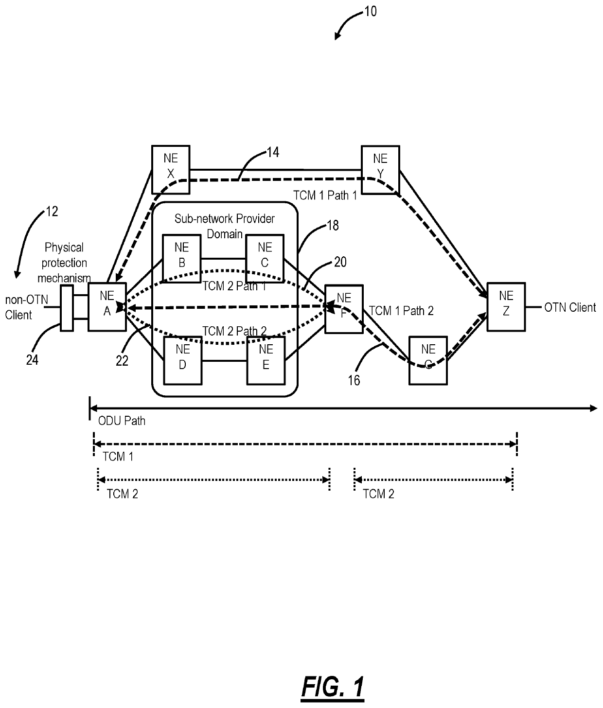
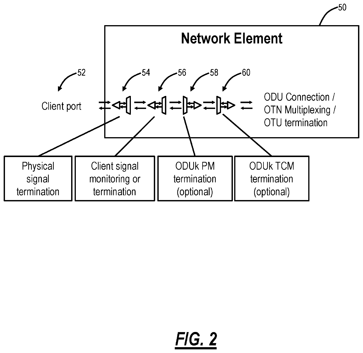
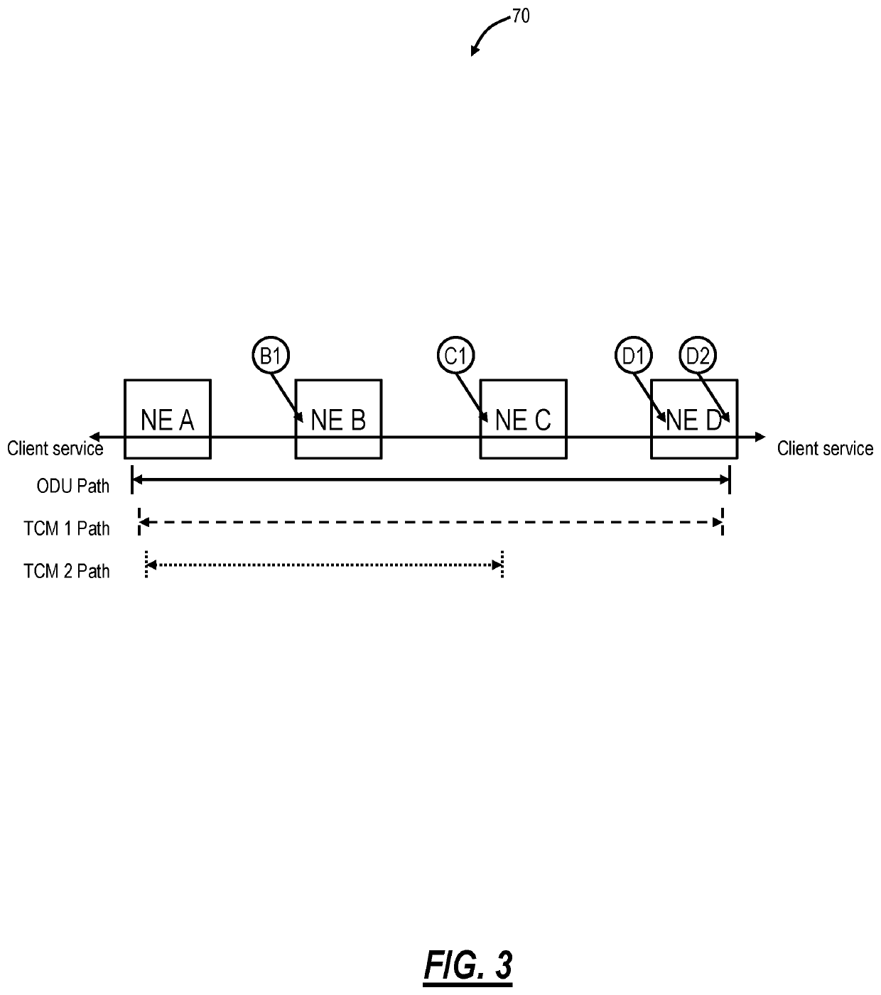
[0025]The present disclosure relates to systems and methods for generic non-client specific protection via Tandem Connection Monitoring (TCM) status and enhanced OTN network propagation of client faults. In an embodiment, the present disclosure uses status at a TCM layer to communicate the faults to the far end for triggering a far end protection switch. The TCM layer can be any of TCM1 to TCM6 for the ODU path and can even be communicated in multiple TCM layers simultaneously to allow for far end visibility at multiple points throughout the network. This allows protection to be closed at earlier locations within the provider's network if they so choose. A TCM could be enabled for only a portion of the network, and if protection is closed and the TCM terminated, then subsequent nodes would not experience the failed TCM status. In another embodiment, the present disclosure enhances the ability to propagate client status to the far end, at any, or several, of the ODU Performance Monit...


PUM


Abstract

A network element includes a client port configured to receive a signal for transmission; a line port configured to transmit the signal to a far end via Optical Transport Network (OTN); circuitry configured to communicate one or more of a fault and a status associated with the signal to the far end via OTN overhead. The circuitry configured to communicate can be for the fault and utilizes one or more Tandem Connection Monitoring (TCM) layers in the OTN overhead. The circuitry configured to communicate can be for the status and utilizes one or more of Optical Data Unit (ODU) Performance Monitoring (PM) and one or more Tandem Connection Monitoring (TCM) layers.

Description

FIELD OF THE DISCLOSURE[0001]The present disclosure generally relates to networking, namely Optical Transport Network (OTN). More particularly, the present disclosure relates to systems and methods for generic non-client specific protection via Tandem Connection Monitoring (TCM) status and enhanced OTN network propagation of client faults.BACKGROUND OF THE DISCLOSURE[0002]OTN is defined in, for example, ITU-T Recommendation G.709 (June / 2016) “Interfaces for the Optical Transport Network (OTN),” ITU-T Recommendation G.798 (December / 2017) “Characteristics of optical transport network hierarchy equipment functional blocks,” etc., the contents of which are incorporated by reference herein. OTN networks and standards employ line and path level protection but may require additional non-standard capabilities for physical layer protection. Optical Data Unit (ODU) and TCM path status typically reflects the status between the origination and termination points of the ODU and TCM path, whereas...

Claims


Application Information

Patent Timeline
Patent Type & Authority Patents(United States)
IPC IPC(8): H04B10/032H04B10/079H04B10/27
CPCH04B10/032H04B10/07951H04B10/27H04B10/0793H04J14/0287H04Q11/0062H04Q2011/0081H04Q2011/0084
Inventor IBACH, TREVOR JOHNBABINEAU, LARRY
Owner CIENA
Why Eureka
Try Eureka