
Systems and method for use of single mass flywheel alongside torsional vibration damper assembly for single acting reciprocating pump

a technology of torsional vibration damper and flywheel, which is applied in the direction of machines/engines, liquid fuel engines, positive displacement liquid engines, etc., can solve the problems of high and low frequency torsional vibration through the driveline, damage and premature wear of driveline components including prime mover, and torque output variances may create shock loading in the pump and driving equipment, so as to reduce or eliminate upstream shock loading, dampen torsional resonance, and reduce or eliminate the effect of pump imposed

Active Publication Date: 2021-05-25
BJ ENERGY SOLUTIONS LLC
View PDF996 Cites 46 Cited by
  • Summary
  • Abstract
  • Description
  • Claims
  • Application Information

AI Technical Summary

Benefits of technology

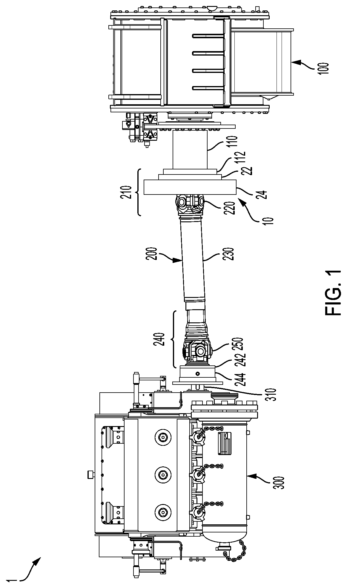
[0007]This disclosure relates generally to vibration dampening assemblies for use with pump systems including a reciprocating pump and driving equipment configured to cycle the pump. The vibration dampening assemblies may include single mass flywheel(s) and / or torsional vibration dampener(s) to reduce or eliminate upstream shock loading and / or dampen torsional resonance from reaching the driving equipment; i.e., to reduce or eliminate pump imposed high frequency / low amplitude and low frequency / high amplitude torsional vibrations.
[0008]According to some embodiments, a single mass flywheel or a series of single mass flywheels along the drive-train system components between the gear box or transmission and input shaft of a reciprocating pump may be used to reduce output speed fluctuations that may cause vibrational and torsional effects on the gearbox and engine. Further, at least one torsional vibration dampener may be connected to the drive-train system to dampen the harmonic effects of the reciprocating pump. According to some embodiments, the at least one flywheel and the at least one torsional damper may not require electrical control to be able to function, but it is contemplated that electrical sensors and instrumentation may be present to monitor the condition of the drive line.

Problems solved by technology

During fracturing operations, high and low frequency torsional vibration is a common occurrence through the driveline.
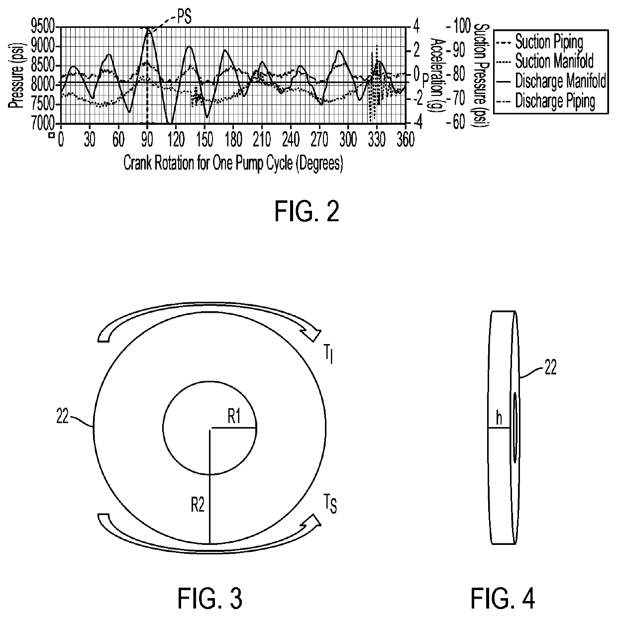
As noted, the nature of the suction and discharge strokes of the reciprocating pump generate variable torque spikes that originate from the discharge of high pressure fluid and may migrate through the drive line and cause damage and premature wear on the driveline components including the prime mover.
Problematically, each reciprocating pumps operating in the field generally have their own torsional vibration frequency and amplitude profile that is dependent upon the selected operational pressure and rate.
Another problem arises when a group of reciprocating pumps are connected to a common discharge line.
The torque output variances may create shock loading in the pump and in the driving equipment upstream from the pump.
This shock loading may shorten the life of the driving equipment including causing failure of one or more components of the driving equipment.
This torsional resonance may shorten the life of the driving equipment including causing failure of one or more components of the driving equipment.

Method used


Image

  • Systems and method for use of single mass flywheel alongside torsional vibration damper assembly for single acting reciprocating pump
  • Systems and method for use of single mass flywheel alongside torsional vibration damper assembly for single acting reciprocating pump
  • Systems and method for use of single mass flywheel alongside torsional vibration damper assembly for single acting reciprocating pump

Examples


Embodiment Construction

[0031]The present disclosure will now be described more fully hereinafter with reference to example embodiments thereof with reference to the drawings in which like reference numerals designate identical or corresponding elements in each of the several views. These example embodiments are described so that this disclosure will be thorough and complete, and will fully convey the scope of the disclosure to those skilled in the art. Features from one embodiment or aspect may be combined with features from any other embodiment or aspect in any appropriate combination. For example, any individual or collective features of method aspects or embodiments may be applied to apparatus, product, or component aspects or embodiments and vice versa. The disclosure may be embodied in many different forms and should not be construed as limited to the embodiments set forth herein; rather, these embodiments are provided so that this disclosure will satisfy applicable legal requirements.

[0032]As used i...


PUM


Abstract

A pump system may include a pump, a driveshaft, driving equipment, and a vibration dampening assembly configured to reduce pump-imposed high frequency / low amplitude and low frequency / high amplitude torsional vibrations. The pump may have an input shaft connected to the driveshaft. The driving equipment may include an output shaft having an output flange connected to the driveshaft. The driving equipment may be configured to rotate the driveshaft to rotate the input shaft of the pump therewith. The vibration dampening assembly may include one or more flywheels operably connected to the input shaft and configured to rotate therewith.

Description

PRIORITY CLAIMS[0001]This U.S. non-provisional patent application claims priority to and the benefit of, under 35 U.S.C. § 119(e), U.S. Provisional Application No. 62 / 899,963, filed Sep. 13, 2019, and U.S. Provisional Application No. 62 / 704,560, filed May 15, 2020, the disclosures of both of which are incorporated herein by reference in their entireties.BACKGROUNDTechnical Field[0002]The present disclosure relates to single acting reciprocating pumps and, more specifically, to single mass flywheels and torsional vibration dampers for use with single acting reciprocating pumps.Discussion of Related Art[0003]During fracturing operations, high and low frequency torsional vibration is a common occurrence through the driveline. Such torsional vibration is typically generated via the operation of a reciprocating pump. Reciprocating pumps are driven to pump “slugs” of fluid with as the pump reciprocates or cycles. The speed and operating pressure of the pump influences the amount of fluid ...

Claims


Application Information

Patent Timeline
Patent Type & Authority Patents(United States)
IPC IPC(8): F04B53/00F16F15/315F16F15/12F16F15/14F04B17/00
CPCF04B53/003F04B17/00F16F15/1202F16F15/1457F16F15/3153F16F15/12F16F2222/12F16F2238/02
Inventor YEUNG, TONYRODRIGUEZ-RAMON, RICARDORODRIGUEZ, GUILLERMOSETH, SAMIR NATH
Owner BJ ENERGY SOLUTIONS LLC
Learn More