Variable stem for human-powered vehicle

a human-powered vehicle and variable stem technology, applied in the direction of steering devices, cycle brakes, cycle equipment, etc., can solve the problem of not being able to adjust the height of the handlebar

Active Publication Date: 2021-06-15
SHIMANO INC
View PDF23 Cites 0 Cited by
  • Summary
  • Abstract
  • Description
  • Claims
  • Application Information

AI Technical Summary

Benefits of technology

[0008]With the variable stem according to the second aspect, it is possible to easily engage and disengage the positioning structure to adjust a position of the stem body.
[0026]With the variable stem according to the eleventh aspect, it is possible to provide a rider with a more comfortable ride by controlling the variable stem in accordance with information relating to a driving state of the human powered-vehicle.

Problems solved by technology

However, the height of a handlebar is not adjustable while in a driving state.

Method used


Image

  • Variable stem for human-powered vehicle
  • Variable stem for human-powered vehicle
  • Variable stem for human-powered vehicle

Examples


first embodiment

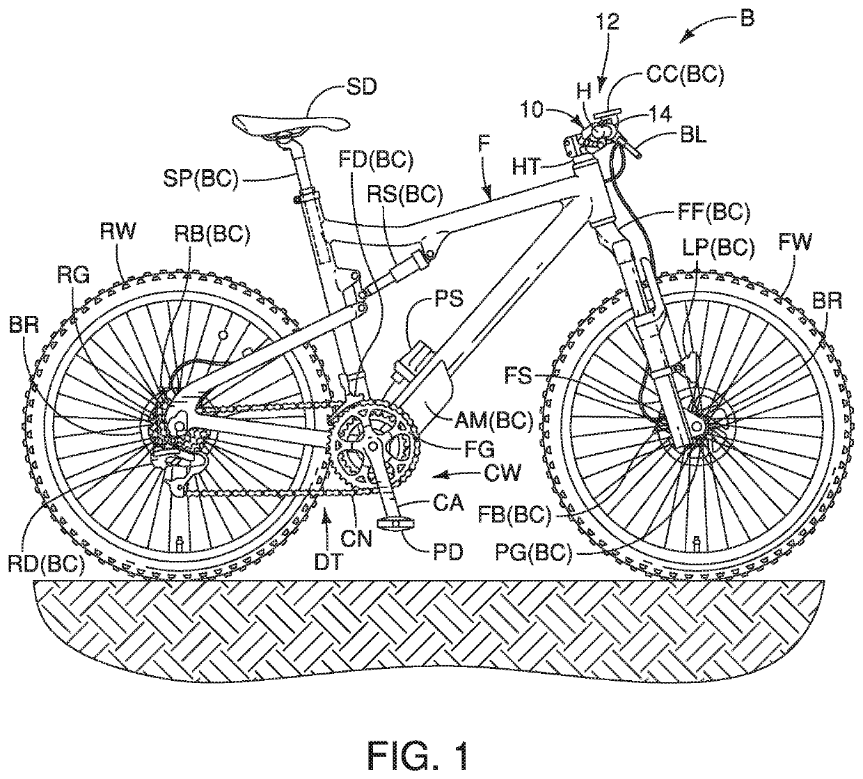
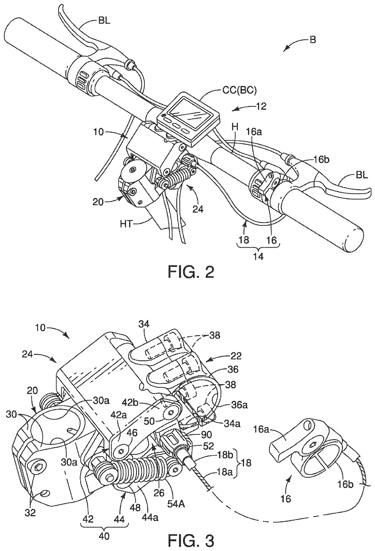
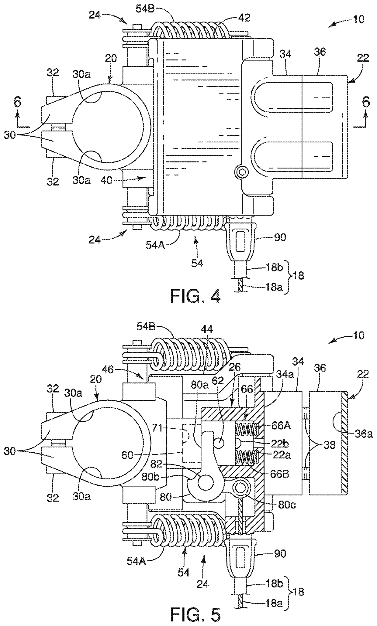
[0067]In the first embodiment, the variable stem 10 basically comprises a head tube mount 20, a handlebar mount 22, a stem body 24 and a positioning structure 26. Basically, the head tube mount 20 is configured to be mounted to a steerer tube or head tube HT of the front fork FF, while the handlebar mount 22 is configured to be mounted to the handlebar H. The stem body 24 couples the handlebar mount 22 to the head tube mount 20. In this way, the variable stem 10 is rigidly mounted to the head tube HT of the front fork FF and supports the handlebar H for turning the front fork FF and the front wheel FW with respect to the frame F.

[0068]The controller 14 is configured to control the positioning structure 26 while the human-powered vehicle B is in a driving state. Specifically, the controller 14 controls the positioning structure 26 to change the position of the handlebar H with respect to the frame F. More specifically, the controller 14 controls the positioning structure 26 to change...

third embodiment

[0087]In this third embodiment, the variable stem 210 comprises an electronic controller 214 and an electric actuator or motor 215 for controlling the positions of the variable stem 210. As seen in FIG. 14, the variable stem 210 further comprises the operating device 116 which is electrically connected to the electric motor 215 by an electrical cord 218. In this way, the variable stem 210 includes a manually operated controller (the operating device 116 and the electrical cord 218, which form a physically operated controller) for the user to manually control the positions of the variable stem 210 via the electric motor 215. The electronic controller 214 is also electrically connected to the electric motor 215 by the electrical cord 218. In this way, the electronic controller 214 is configured to automatically control the positions of the variable stem 210 via the electric motor 215 as explained below.

[0088]Thus, in the third embodiment, the variable stem 210 includes the stem body 2...


PUM


Abstract

A variable stem for a human-powered vehicle basically includes a head tube mount, a handlebar mount, a stem body, a positioning structure and a controller. The stem body couples the handlebar mount to the head tube mount. The stem body is configured to be moved between a first position and a second position. The handlebar mount is disposed at a different location with respect to the head tube mount with the stem body in the first position as compared to the stem body being in the second position. The positioning structure is configured to selectively position the stem body between a first position and a second position. The controller is configured to control the positioning structure while the human-powered vehicle is in a driving state.

Description

BACKGROUNDTechnical Field[0001]The present disclosure generally relates to a variable stem for a human-powered vehicle and / or a component control system having the variable stem.Background Information[0002]A human-powered vehicle is often provided with a handlebar that is used for steering a wheel or a pair of wheels. A stem is sometimes used to connect the handlebar to a steering part of a steering system. For example, a stem is often used in a bicycle to connect the handlebar to a bicycle steerer tube steering column of the bicycle. One example a stem used with a bicycle is disclosed in European Patent Publication Application No. EP 2 042 419 A1. Some human-powered vehicles include components that are controlled in response to manual operation of a user operated input mounted on the human-powered vehicle. Examples of components that are controlled in response to operation of an operating device include a suspension, a height adjustable seatpost, a shifting device and a braking sys...

Claims


Application Information

Patent Timeline
Patent Type & Authority Patents(United States)
IPC IPC(8): B62K21/16B62K23/02B62J99/00B62J1/08B62K25/04B62M25/08B62M6/45B62L3/00B62J6/01B62J45/20
CPCB62K21/16B62J1/08B62J6/01B62J99/00B62K23/02B62K25/04B62L3/00B62M6/45B62M25/08B62J45/20B62J2001/085B62K2025/044B62J6/02B62L3/02B62J45/41B62J45/411B62J45/414B62J45/4151B62K23/06B62K25/08B62K25/30B62M6/55B62M2025/006
Inventor HARA, NOBUKATSU
Owner SHIMANO INC
Why Eureka
Try Eureka