
Gutter insert

a technology of inserts and gutters, applied in the field of gutter inserts, can solve the problems of completely changing the exterior look, the system described is not designed to be retrofitted, and the leaves and debris buildup at the interior and exterior corners, etc., to achieve the effect of simple and efficient installation, improved flow characteristics of the sharp-edged interior, and easy installation and installation

Active Publication Date: 2021-06-15
BALDASSI JAMES
View PDF19 Cites 1 Cited by
  • Summary
  • Abstract
  • Description
  • Claims
  • Application Information

AI Technical Summary

Benefits of technology

[0007]Unfortunately, none of the prior art describes a gutter inset which can be used easily and without difficulty installed into existing gutter or eaves trough configurations which have sharp edged interior and exterior corner joints without the need for completely renewing the eaves trough installation and without changing the exterior visual appearance of the existing gutter system. There is a need for improving the flow characteristics of the sharp-edged interior and exterior corner joints of conventional gutter systems without expensive complete re-installations or modifications to the sharp edged corners and without changing the existing exterior look of the gutters and gutter corners.
[0008]It is an object of the present concept to provide a simple and efficient rain gutter corner insert that minimizes turbulent flow around sharp edged corners and the buildup of leaves and debris at the interior and exterior corners of a rain gutter and which will promote both self-flushing of the gutter trough as well as simplify cleaning of gutter corners.SUMMARY OF THE INVENTION
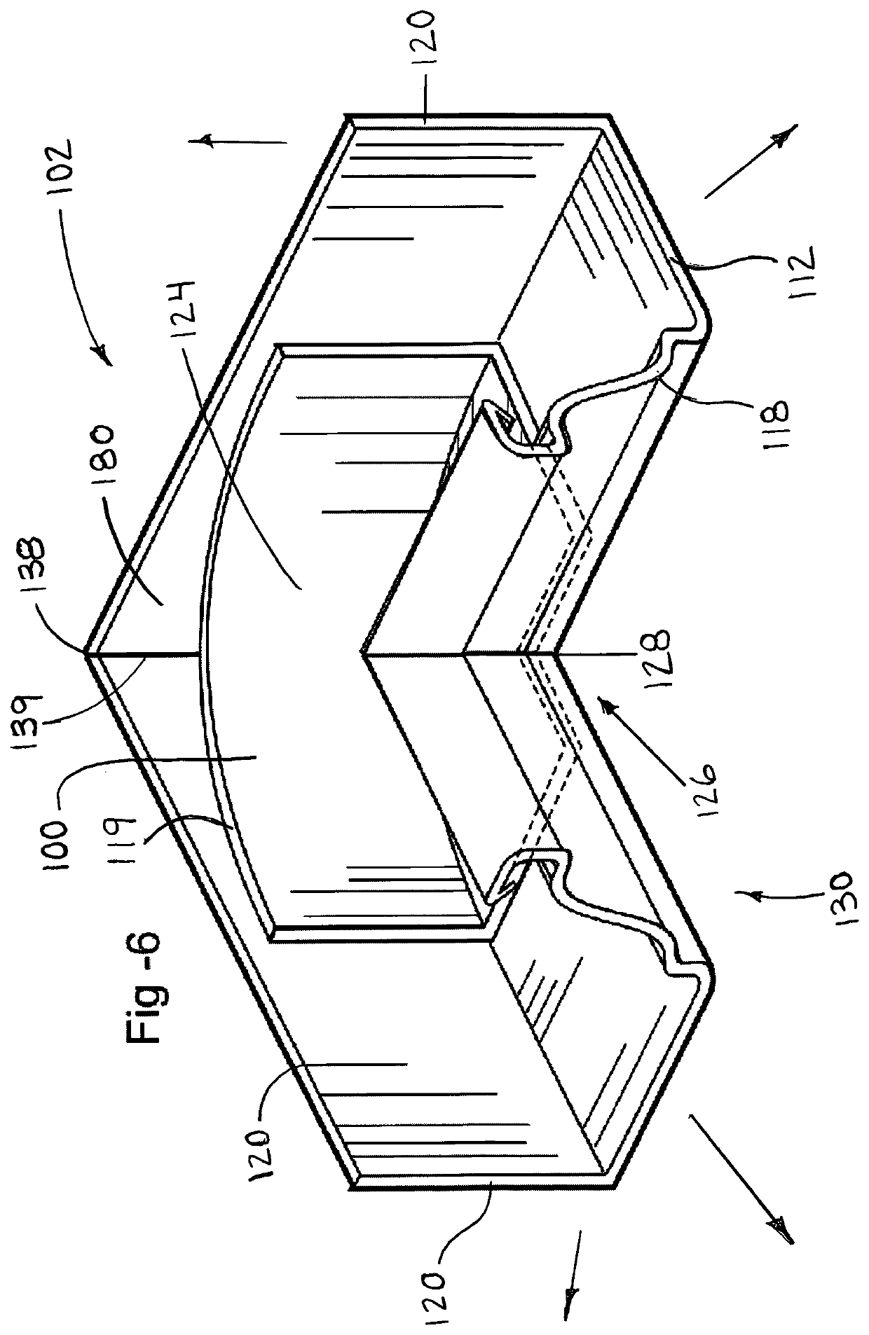
[0015]Preferably wherein the inner peripheral edge is a V shape to follow the contour of the inner corner portion of the corner section of an eaves trough, wherein the inner apex of the corner section of an eaves trough is adjacent to an apex of the V shaped peripheral edge thereby preventing longitudinal movement of the gutter insert in an installed position within the corner section of an eaves trough.

Problems solved by technology

Unfortunately, these sharp edge interior and exterior corner joints due to the creation of turbulence at these joints tends to result in the buildup of leaves and debris at the interior and exterior corners of the corner sections of the eaves trough due to whirlpools, eddies and other non-uniform flow around the sharp edge interior and exterior corner joints.
The system described is not designed to be retrofitted to a conventional gutter system and completely changes the exterior look.
This patent explains that sharp edged corner joints tend to fail in part due to the accumulation of leaves and debris at the corner joint creating damming and potential ice damage as a result.
Unfortunately, none of the prior art describes a gutter inset which can be used easily and without difficulty installed into existing gutter or eaves trough configurations which have sharp edged interior and exterior corner joints without the need for completely renewing the eaves trough installation and without changing the exterior visual appearance of the existing gutter system.

Method used


Image

  • Gutter insert
  • Gutter insert
  • Gutter insert

Examples


Embodiment Construction

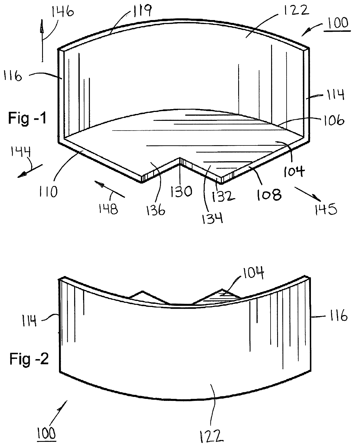
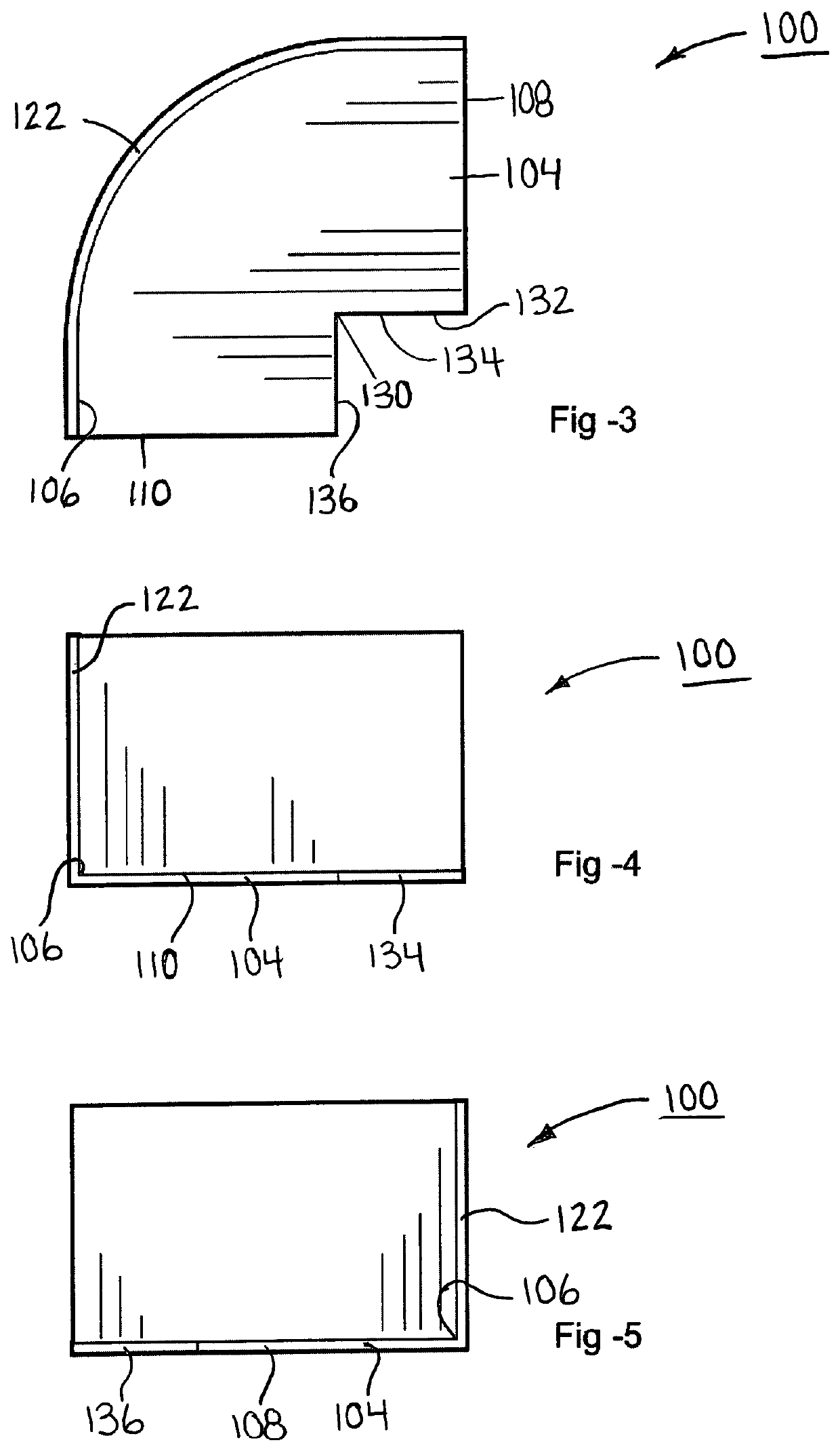
[0036]The present concept is shown in FIGS. 1-6 for a gutter insert 100 for an inside corner and FIGS. 7-12 which is a gutter insert 200 for an outside corner. The inside corner 100 and outside corner 200 have many similarities in that both include a bottom wall 104, 204 and a back wall 122, 222.

[0037]Referring first of all to FIGS. 1-6 a gutter insert for an inside corner of a gutter or eaves trough is shown generally as 100.

[0038]Gutter insert 100 includes the following major components, namely bottom wall 104 which is rigidly connected to an upstanding curved or arcuate back wall 122 at back periphery 106.

[0039]Bottom wall 104 includes an inner peripheral edge 132 which includes a first arm 134 and a second arm 136 which meet at apex 130. Gutter insert for an inside corner 100 further includes a first transverse edge 108 and a second transverse edge 110. First transverse edge 108 includes a first upstanding edge 114 and second transverse edge 110 includes a second upstanding edge...


PUM


Abstract

The present concept is a gutter insert designed to fit within the corner section of an eaves trough. The gutter insert includes a substantially horizontal bottom wall which includes an arcuate back periphery, and an inner peripheral edge and an upstanding back wall rigidly connected to the horizontal bottom surface at the arcuate back periphery of the horizontal bottom wall, wherein the upstanding back wall together with the horizontal bottom wall define a first and a second transverse edge, which include a first and second upstanding edge respectively. The horizontal bottom wall is configured to lie adjacent to a base of the corner section of an eaves trough and extends between the inner sidewall and an outer sidewall of corner section of an eaves trough at the first and second transverse edges. The inner peripheral edge is configured to lie substantially adjacent an inner sidewall of the corner section of an eaves trough such that the horizontal bottom wall, the upstanding back wall of the gutter insert, together with an inner side wall of the corner section of an eaves trough form a channel directing the flow of water smoothly around the corner of a corner section of an eaves trough.

Description

FIELD OF THE INVENTION[0001]The present device relates to an insert for corner sections of a conventional eavestroughing and more particularly relates to a gutter insert for an inside corner and a gutter insert for an outside corner of conventional gutters or eavestroughing.SUMMARY OF THE INVENTION[0002]A gutter or eaves trough for the purpose of this application is a shallow trough fixed at the edge of a roof for carrying off rainwater. Gutter and eaves trough are used interchangeably herein and refer to the same thing. Conventional commonly used gutters or eaves trough are manufactured from roll formed sheet aluminum and are attached to the fascia board of the roof edge of a house using various attachment mechanisms that are commonly available. Inside corners and the outside corners of a conventional eaves trough system is normally simply a mitered corner which either the installer miters on site from the straight sections of formed gutter or eaves trough or may be pre-mitered ins...

Claims


Application Information

Patent Timeline
Patent Type & Authority Patents(United States)
IPC IPC(8): E04D13/064
CPCE04D13/0643
Inventor BALDASSI, JAMES
Owner BALDASSI JAMES
Learn More