Extrusion die manufacturing method

a technology of extrusion dies and manufacturing methods, applied in the direction of additive manufacturing processes, manufacturing tools, electric/magnetic/electromagnetic heating, etc., can solve the problems of insufficient design flexibility, inability to form elements located within the interior of the die, and most machining techniques utilized for forming these extrusion dies are limited to “line-of-sight” elements, etc., to achieve the effect of improving the flow characteristics of the extrusion die, reducing time and cos

Inactive Publication Date: 2008-05-29
CORNING INC
View PDF12 Cites 38 Cited by
  • Summary
  • Abstract
  • Description
  • Claims
  • Application Information

AI Technical Summary

Benefits of technology

[0018]The present inventive method for manufacturing an extrusion die produces a single-piece, integrally-formed die with a relatively high structural integrity, while allowing blind-elements to be formed on the interior thereof so as to improve the flow characteristics of the extrusion die as desired. Further, the desired method reduces the time and cost typically associated with the formation of extrusion dies, and is particularly well suited for the required purpose.

Problems solved by technology

Heretofore, most machining techniques utilized for forming these extrusion dies are limited to “line-of-sight” elements.
Specifically, these techniques cannot be employed to form elements located within an interior of the die that may not be easily accessed or accessed in a straight line from an outer surface of the billet from which the die is machined.
While other techniques have been employed to allow the formation of extrusion dies with blind-elements therein, these techniques do not allow for sufficient flexibility of design and are incapable of forming certain die details.
One shortcoming of such dies is added cost and time required in forming such dies, as well as a relative decreased structural integrity as a result of forming the die out of multiple bonded pieces as compared to forming the die from a single-piece billet.
However, the required use of the binder within these processes necessarily results in limitations for their use.
Specifically, certain details formed within the pre-sintered dies do not retain sufficient shape, or in some cases cannot survive, the sintering process.
However, as the part is sintered, a significant portion of the binder material is burned off and the strength of part approaches 3000 psi to 5000 psi prior just to sintering of the metal powder.
As a result, distortion of fragile details may occur within the die.
Further, certain details, such as those that would be suspended from a portion of the pre-sintered die, do not survive the sintering process.
Any one of the methods described above may also be relatively time consuming and expensive, with the average time to building ranging from days to weeks, at significant cost.

Method used


Image

  • Extrusion die manufacturing method
  • Extrusion die manufacturing method
  • Extrusion die manufacturing method

Examples


Embodiment Construction

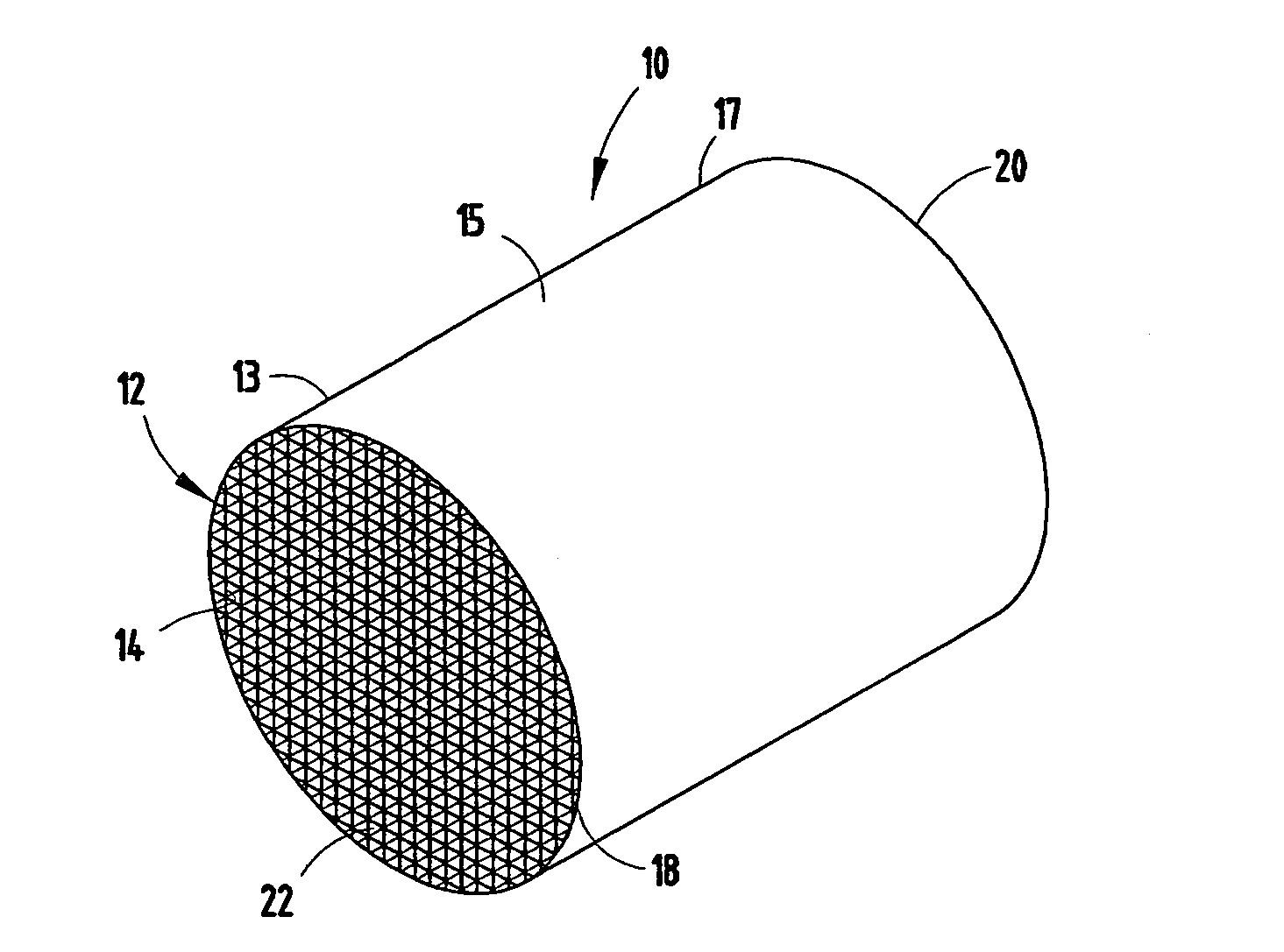
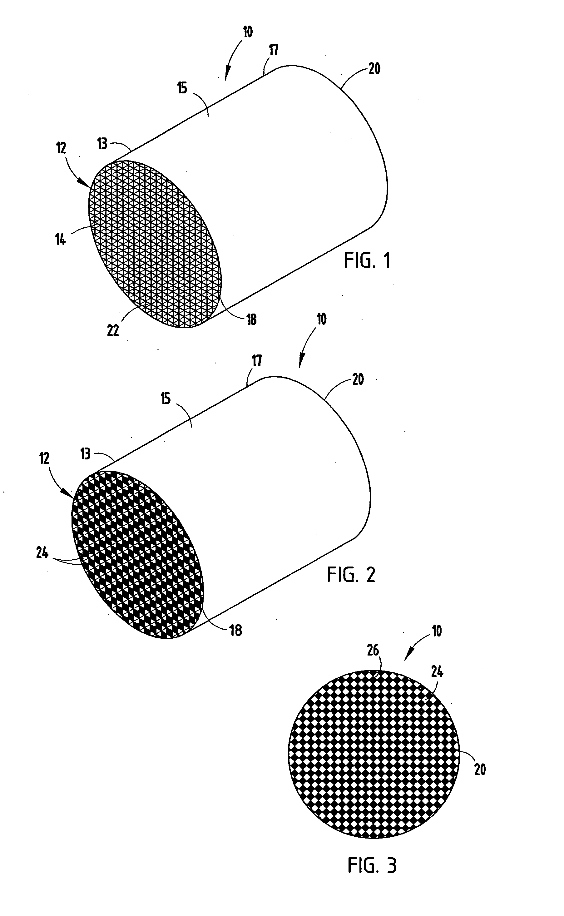
[0033]For purposes of description herein, the terms “upper,”“lower,”“right,”“left,”“rear,”“front,”“vertical,”“horizontal,” and derivatives thereof shall relate to the invention as oriented in FIGS. 1 and 5. However, it is to be understood that the invention may assume various alternative orientations and step sequences, except where expressly specified to the contrary. It is also to be understood that the specific devices and processes illustrated in the attached drawings, and described in the following specification are exemplary embodiments of the inventive concepts defined in the appended claims. Hence, specific dimensions and other physical characteristics relating to the embodiments disclosed herein are not to be considered as limiting, unless the claims expressly state otherwise.

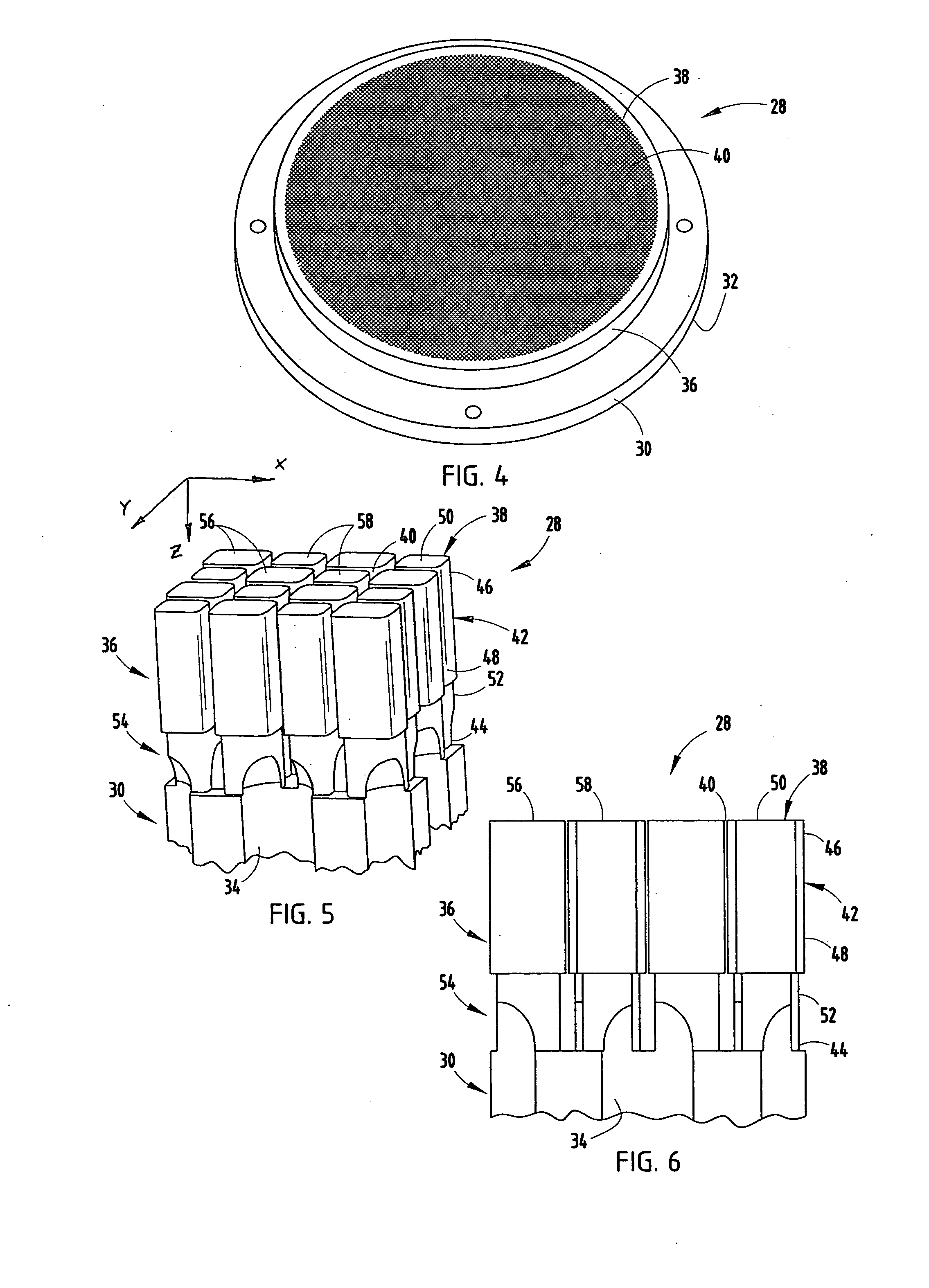
[0034]The present inventive method includes the solidifying of superposed layers of powdered materials, such as metals and ceramics, to form an extrusion die 28 (FIG. 4-6). Specifically, the method inc...


PUM

PropertyMeasurementUnit
thicknessaaaaaaaaaa
depthaaaaaaaaaa
depthaaaaaaaaaa

Abstract

A method of forming an extrusion die comprises depositing at least one layer of a sinterable material, such as binder-free sinterable material, in a plane creating a layer of unsintered material, applying irradiation to the at least one layer of unsintered material along a pattern creating a layer of centered material, and forming the extrusion die as a single, integrally-formed piece by repeating the depositing and irradiating steps in a coordinate direction that is substantially orthogonal to the plane, wherein a new layer is superposed upon a previously sintered layer. The extrusion die formed via this method includes an inlet section having a die inlet face and a plurality of feed channels extending from the inlet face toward a honeycomb-forming section that is spaced from the inlet face and terminates in a die outlet face that includes an array of discharge channels formed from pins. Dies having at least two of the pins coupled to one another by a structural element other than at the pin root may be manufactured by the method.

Description

FIELD OF THE INVENTION[0001]The present invention relates to extrusion dies and a method for forming an extrusion die that may be utilized for forming honeycomb structures. More particularly, the invention relates to high-strength, single-piece, integrally-formed extrusion dies and methods for forming such extrusion dies.DESCRIPTION OF RELATED ART[0002]Honeycomb structures having traverse cross-sectional cellular densities of approximately one tenth to one hundred or more per square centimeter have several uses, including catalysts substrates, solid particulate filter bodies and stationary heat exchangers. The manufacture of these honeycomb structures from plasticized powder batches comprising inorganic powders dispersed in appropriate binders is well known. U.S. Pat. Nos. 3,790,654; 3,885,977; and 3,905,743 describe extrusion dies, processes, and compositions for such manufacture, while U.S. Pat. Nos. 4,992,233 and 5,011,529 describe honeycombs of similar cellular structure extrude...

Claims


Application Information

Patent Timeline
Patent Type & Authority Applications(United States)
IPC IPC(8): B29C47/30B29C35/08B29C67/20B29C48/345B29C48/30B29C48/32
CPCB23P15/243B29L2031/60B29C67/0077B29C47/0028B28B3/269B29C64/153B29C48/11
Inventor PETERSON, RICHARD CURWOODSTEPHENS, ALAN THOMAS
Owner CORNING INC
Why Eureka
Try Eureka