Check patentability & draft patents in minutes with Patsnap Eureka AI!

Touch module

a technology of input module and touch pad, which is applied in the field of input module, can solve the problems of erroneously touching the switching key or pressing down the touchpad to generate an erroneous pressing signal, and conventional touchpads are not user-friendly, so as to prevent erroneously switching the function mode

Active Publication Date: 2021-06-15
PRIMAX ELECTRONICS LTD
View PDF10 Cites 0 Cited by
  • Summary
  • Abstract
  • Description
  • Claims
  • Application Information

AI Technical Summary

Benefits of technology

Enables quick and accurate switching between function modes, reducing the likelihood of erroneous operations and enhancing user experience by preventing accidental triggering of the mode-adjusting switch.

Problems solved by technology

If the switching key is installed on the touchpad, some drawbacks possibly occur.
For example, when the user operates the touchpad in a different function mode, the user may erroneously touch the switching key or press down the touchpad to generate an erroneous pressing signal.
In other words, the conventional touchpad is not user-friendly.

Method used


Image

  • Touch module
  • Touch module
  • Touch module

Examples


first embodiment

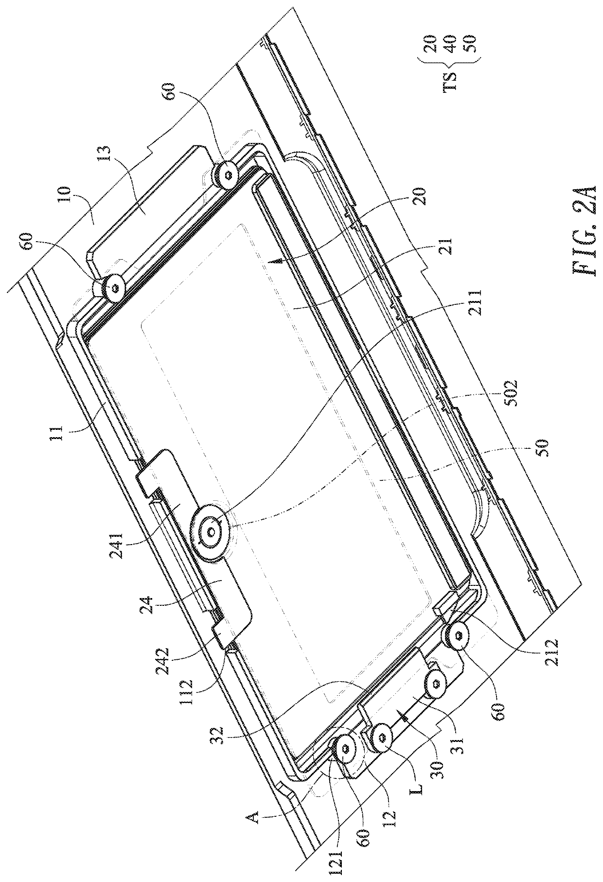
[0044]Please refer to FIGS. 2A and 4A. FIG. 4A schematically illustrates the operations of the touch module according to the present invention. In the situation (i) of FIG. 4A, the second end part 32 of the stopping pin 30 is not inserted into the vertical gap G2 between the touchpad 20 and the supporting plate 50. Meanwhile, the stopping pin 30 and the touchpad 20 do not interfere with each other. While the touchpad 20 is pressed by the user, the touchpad 20 is swung in the vertical gap G2 by using the connection seat 40 as a fulcrum. Consequently, the pressing switch 211 is contacted with the pressing block 502 of the supporting plate 50 to generate a corresponding pressing signal.

[0045]In the situation (ii) of FIG. 4A, the switching element 24 or the covering plate 23 exposed to the opening 111 is moved, and the touch structure TS is correspondingly moved to the left. Meanwhile, the second end part 32 of the stopping pin 30 is inserted into the vertical gap G2 between the touchpa...

second embodiment

[0046]Please refer to FIG. 4B. FIG. 4B schematically illustrates the operations of a touch module according to the present invention. The components and functions of the touch module in the situation (i) of FIG. 4B are similar to those of the in the situation (i) of FIG. 4A except for the numbers of the horizontal gaps G1 and the number of the mode-adjusting switches 212. In this embodiment, there is a horizontal gap G1 between a first lateral edge of the touchpad 20 and the inner wall of the accommodation structure 11 and there is another horizontal gap G1 between a second lateral edge of the touchpad 20 and the inner wall of the accommodation structure 11. Moreover, two mode-adjusting switches 212 are disposed on the bottom surface of the touchpad 20 and located at two opposite sides.

[0047]In the situation (ii) of FIG. 4B, the switching element 24 or the covering plate 23 exposed to the opening 111 is moved, and the touch structure TS is correspondingly moved to the left. Meanwhil...


PUM


Abstract

A touch module for an electronic device includes a casing, a touch structure and at least one stopping pin. The casing includes an accommodation structure. The accommodation structure is formed on a bottom surface of the casing. The accommodation structure includes an opening. A of the touch structure touchpad is installed in the accommodation structure. There is a horizontal gap between a lateral edge of the touchpad and an inner wall of the accommodation structure. The stopping pin is fixed on the bottom surface of the casing and aligned with a vertical gap of the touch structure. While the touch structure is moved in a first direction or a second direction through the at least one horizontal gap, the stopping pin is inserted into the vertical gap or detached from the vertical gap.

Description

FIELD OF THE INVENTION[0001]The present invention relates to an input module, and more particularly to a touch module for an electronic device.BACKGROUND OF THE INVENTION[0002]A touchpad is an input module that allows the user's finger to press or slide on a smooth panel to operate of the electronic device. Since the touchpad is very thin, the touchpad is usually applied to a notebook computer, a smart phone, a personal digital assistant (PDA) or any other appropriate electronic device.[0003]Generally, the touch function of the touchpad can move a cursor or control the windows, and achieve the functions as the left and right buttons of a mouse. With increasing development of science and technology, the touchpad can be operated in various function modes (e.g., a calculator mode or a quick function mode). According to the existing technology, a switching key is installed on the electronic device or the touchpad. For switching the function mode of the touchpad, it is necessary to press...

Claims


Application Information

Patent Timeline
Patent Type & Authority Patents(United States)
IPC IPC(8): G06F3/0354G06F3/02G06F1/16G06F3/038
CPCG06F3/03547G06F1/1671G06F3/02G06F3/038G06F1/1616G06F1/1662G06F1/169G06F3/0202G06F3/0383
Inventor HUANG, TAI-SOU
Owner PRIMAX ELECTRONICS LTD
Features
  • R&D
  • Intellectual Property
  • Life Sciences
  • Materials
  • Tech Scout
  • Unparalleled Data Quality
  • Higher Quality Content
  • 60% Fewer Hallucinations
Learn More