
Crane assembly

a technology of crane and assembly, which is applied in the direction of hoisting equipment, couplings, runways, etc., can solve the problems of preventing further movement and the effort required to initiate such movemen

Active Publication Date: 2021-06-29
GLOBAL TRACK PTY LTD
View PDF9 Cites 0 Cited by
  • Summary
  • Abstract
  • Description
  • Claims
  • Application Information

AI Technical Summary

Problems solved by technology

One problem with previous crane assemblies occurs when an operator attempts to initiate movement of the bridge in either direction relative to the guides.
The effort required to initiate such movement is often considerable, at least in part owing to the fact that simultaneous movement of both carriages is usually required, although the force is directly applied by the operator only to one carriage.
This applies a torque along the bridge tending to urge the bridge and carriages out of perpendicular alignment, increasing friction, which can ultimately cause jamming, preventing further movement.

Method used


Image

  • Crane assembly
  • Crane assembly

Examples


Embodiment Construction

[0018]The invention is described in detail in conjunction with the attached figures and specific embodiments.

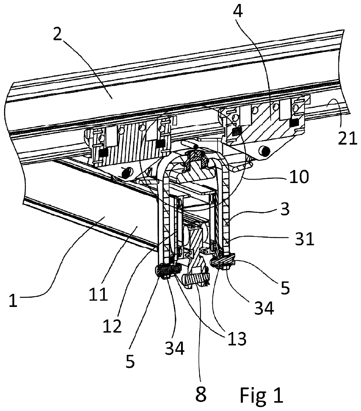
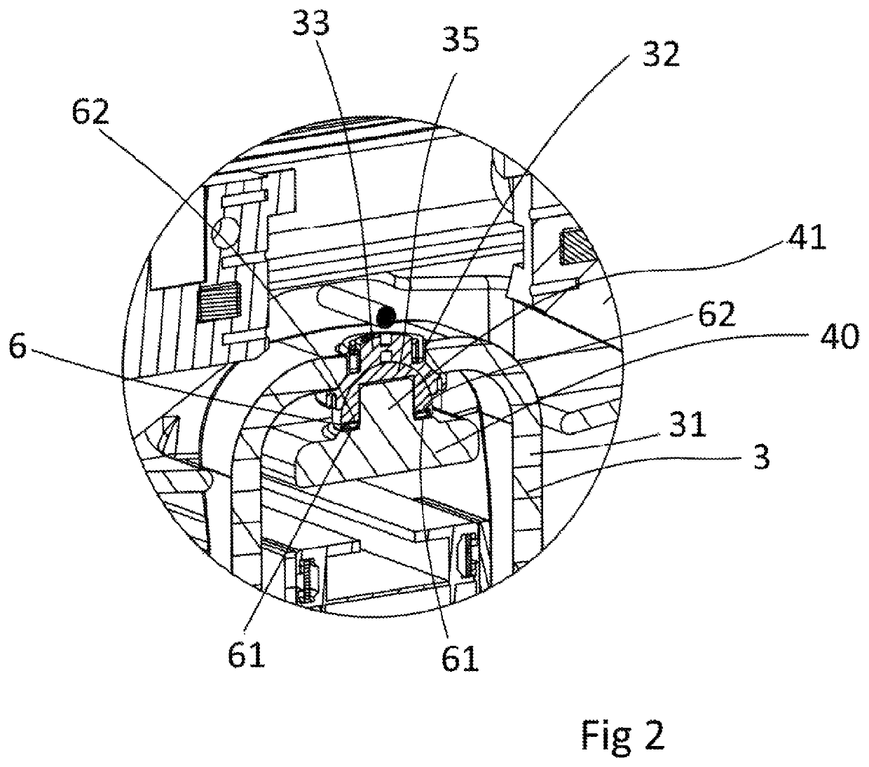
[0019]Referring now to FIGS. 1 and 2, the operation of the invention is illustrated by a truncated cut-through perspective view showing a cross-section through one of the carriages and a centre line of the connector arm. Further details of guides, carriages, bridges and other features are found in prior publications, including the previously published specifications PCT / AU03 / 00668 and PCT / AU2008 / 001731 of the inventor.

[0020]Referring now to FIGS. 1 and 2, the crane assembly comprises a bridge 1 hanging beneath between a pair of parallel guides 2 (only one of the guides being shown). The two ends of bridge 1 are each provided with a connector arm 3 respectively. Carriage 4 is configured to roll along a ledge 21 of guide 2. An opposing ledge is on the other side of guide 2 with a second set of rollers, not visible. Connector arm 3 is shaped like an arch with a top and sides, wi...


PUM


Abstract

The invention provides a crane assembly for lifting a load comprising: a pair of guides (2) positioned parallel to one another; a carriage (4,40) associated with each guide (2) and movable along each guide (2); a bridge (1) having an attachment point (8) for attaching the load, the bridge (1) being attached between the carriages (4,40) through connector arms (3), each connector arm (3) being attached through a lower end (31) to the bridge (1) and pivotable (5) at least about an axis perpendicular to the bridge, each connector arm (3) being attached at an upper end (32) to the corresponding carriage (4,40) through a multi-axis joint (33,35); wherein each multiaxis joint (33,35) is connected to the corresponding carriage (4,40) through a low friction thrust bearing (6) configured to rotate with initial movement of the corresponding carriage (4,40).

Description

CROSS-REFERENCE TO RELATED APPLICATIONS[0001]This application is an U.S. national phase application under 35 U.S.C. § 371 based upon co-pending International Application No. PCT / AU2018 / 050202 filed on Mar. 6, 2018. Additionally, this U.S. national phase application claims the benefit of priority of co-pending International Application No. PCT / AU2018 / 050202 filed on Mar. 6, 2018, and Australia Application No. 201720207355.7 filed on Mar. 6, 2017. The entire disclosures of the prior applications are incorporated herein by reference. The international application was published on Sep. 13, 2018 under Publication No. WO 2018 / 161114 A1.FIELD[0002]The invention relates to one kind of device, more specifically, a crane device that is manually moved.BACKGROUND[0003]Manually operable suspended crane assemblies such as a gantry crane or bridge crane are used in a great variety of industrial and other applications for lifting and moving loads. Such cranes typically suspend the load from a gener...

Claims


Application Information

Patent Timeline
Patent Type & Authority Patents(United States)
IPC IPC(8): B66C5/00B66C5/02B66C9/08B66C9/10B66C9/16B66C17/00B66C19/00F16C11/06F16D3/16
CPCB66C5/02B66C9/08B66C9/10B66C9/16B66C17/00B66C19/00F16C11/06F16D3/16B66C2700/03B66C7/04
Inventor MCKAY, DOUGLAS MCGREGOR
Owner GLOBAL TRACK PTY LTD
Learn More