
furniture hinge

A technology for hinges and furniture, applied in the field of furniture hinges, which can solve the problems of high labor costs in construction and manufacturing, and achieve the effect of low cost

Active Publication Date: 2019-05-14
土耳其萨麦提模子及矿物工商股份公司
View PDF9 Cites 0 Cited by
  • Summary
  • Abstract
  • Description
  • Claims
  • Application Information

AI Technical Summary

Problems solved by technology

These two requirements result in a considerable effort in construction and fabrication

Method used


Image

  • furniture hinge
  • furniture hinge
  • furniture hinge

Examples


Embodiment Construction

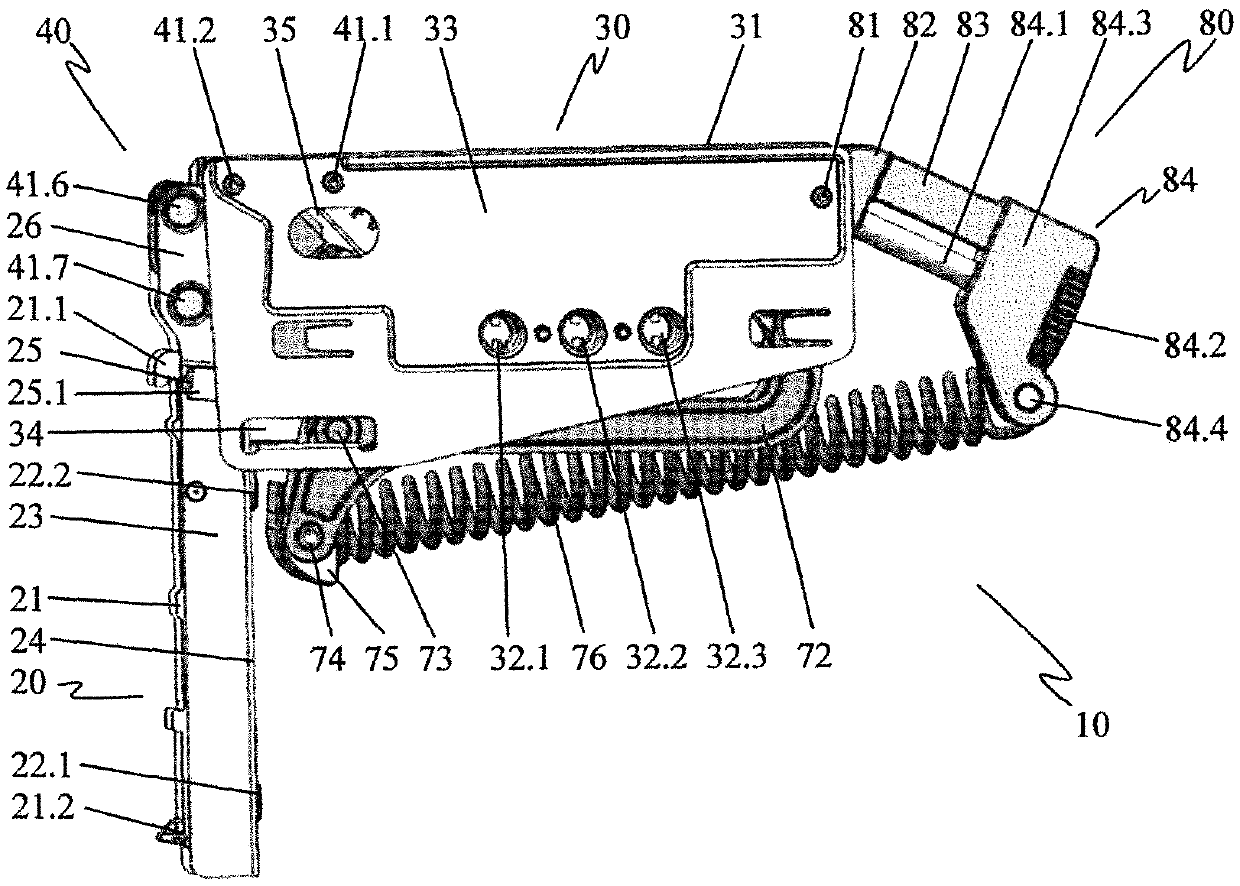
[0033] figure 1 The furniture hinge 10 is shown in a side view with the hinge housing 31 closed in the first end position of the hinge arms 20 folded inward;

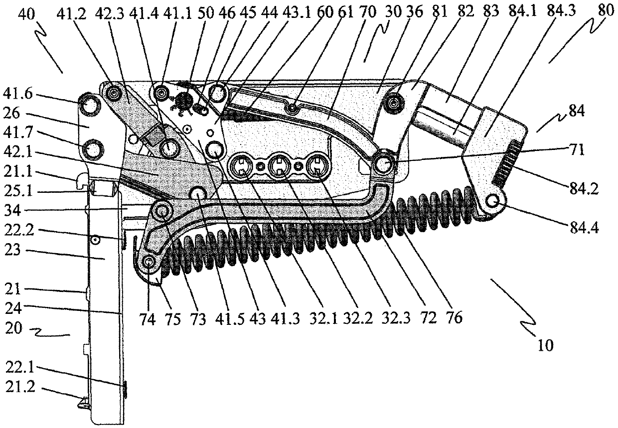
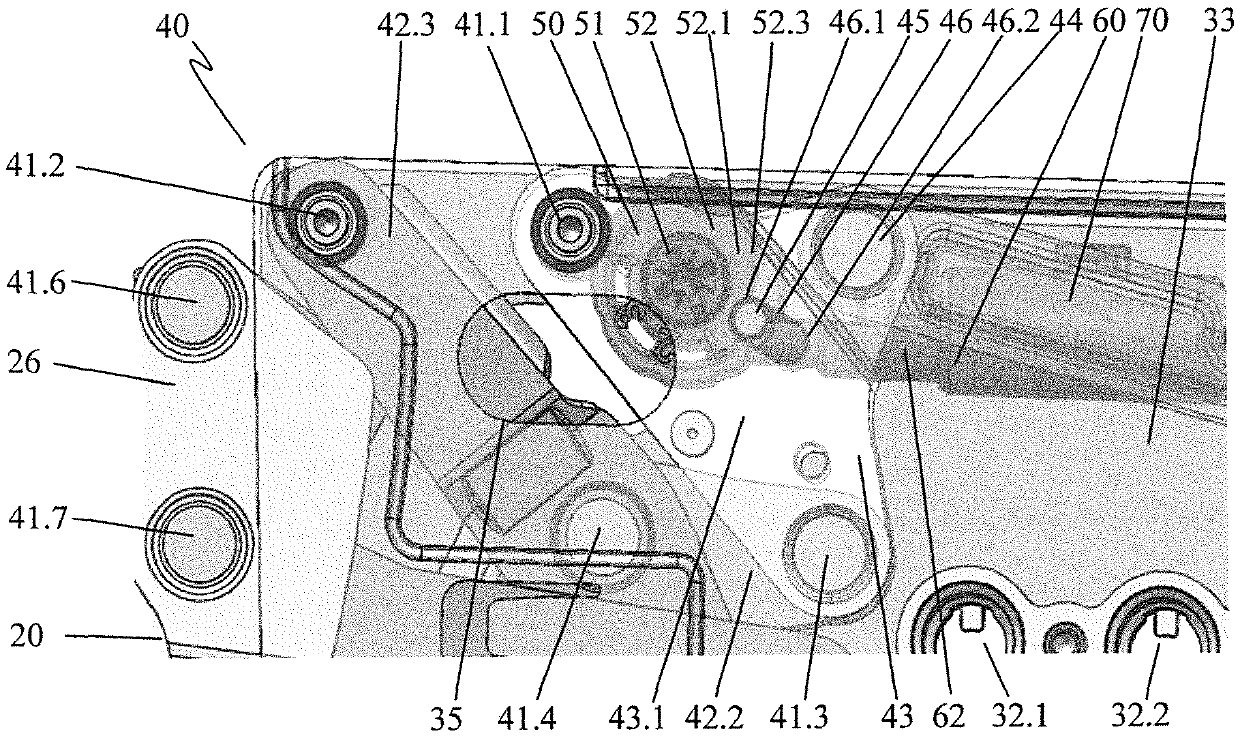
[0034] The hinge housing 31 forms the fastening section 30 of the furniture hinge 10 and has three fastening sockets 32.1, 32.2, 32.3. In the illustration, the hinge housing 31 is closed by a housing cover 33 . A linear guide 34 and an adjustment opening 35 are provided as passage openings in the housing cover 33 . The fastening points of the first joint 41 . 1 , the second joint 41 . 2 and the swivel joint 81 sink into the housing cover 33 .

[0035] The articulated arm 20 is pivotably connected to the fastening section 30 via a polyaxial articulation 40 . The first and second set screws 22 . 1 , 22 . 2 are arranged along the rear web 24 of the hinge arm 20 . The transverse leg 23 adjoins the rear web 24 on either side. The hinge arm 20 engages in a connecting element 21 with connecting hooks 21.1, 21.2. Towards ...


PUM


Abstract

The invention relates to a furniture hinge (10) with a hinge arm (20) and a fastening section (30), wherein the hinge arm (20) and the fastening section (30) are adjustable via a polyaxial joint connection (40) pivotally connected to each other and wherein a damping element (60) damping in the direction of deflection is provided for damping the movement of the hinge arm (20) and for adjusting the hinge arm (20) relative to the fastening section (30) spring (76). It is provided here that the damping element (60) is mounted such that during the folding movement of the hinge arm (20) from the first end position to the second end position, the adjustment of the damping element (60) caused by said folding movement A maximum or minimum deflection of the damping element (60) is performed during the movement. Thus, a furniture hinge is provided which can be produced inexpensively and which allows damped opening and damped closing of the hinge arms.

Description

technical field [0001] The invention relates to a furniture hinge having a hinge part and a fastening section, wherein the hinge part and the fastening section are pivotably interconnected by a polyaxial joint connection, and wherein a damping element is provided for damping in the direction of deflection , for damping the movement of the hinge part, and a spring for readjusting the hinge part relative to the fastening section. Background technique [0002] Such a furniture hinge is known from EP 1 713 996 B1. Therein, an actuator arm driver for a flap of a cabinet is described, the actuator arm driver having a hinge part configured as an actuator arm and fastened to a housing so as to be rotatable about an axis. The actuator arm is connected by a second shaft to a linearly and rotatably mounted control member bearing on its side opposite the control arm by a control curve on a movable pressure member biased by a spring assembly superior. The linear mobility of the contro...

Claims


Application Information

Patent Timeline
Patent Type & Authority Patents(China)
IPC IPC(8): E05D3/16E05D15/40E05F1/10E05F1/12E05F1/14E05F3/00
CPCE05D3/16E05D15/401E05F1/1066E05F1/1269E05F1/14E05F3/00E05Y2600/12E05Y2800/24E05Y2900/20E05F3/20E05Y2201/212
Inventor 阿图尔·希尔齐费尔贝恩德·罗尔德努雷丁·古泽尔特派
Owner 土耳其萨麦提模子及矿物工商股份公司
Learn More