Fuel injection system for internal combustion engines with needle stroke damping

a technology of internal combustion engine and fuel injection system, which is applied in the direction of fuel injection apparatus, charge feed system, spraying apparatus, etc., can solve the problems of inability to adjust the needle stroke, the constant opening pressure of the inner nozzle needle is very vulnerable to tolerance, and the variation of one manufactured item to another makes itself particularly unpleasantly felt, so as to improve the ability, reduce noise, and improve the effect of emissions and nois

Inactive Publication Date: 2005-09-08
ROBERT BOSCH GMBH
View PDF26 Cites 21 Cited by
  • Summary
  • Abstract
  • Description
  • Claims
  • Application Information

AI Technical Summary

Benefits of technology

[0007] The fuel injection system of the invention has the advantage that the opening speed of the inner nozzle needle and thus the injection rate can be adapted. The inner nozzle needle of the Vario nozzle can be switched actively or passively, so that the nozzle opening pressure of the inner nozzle needle can be set in such a way that it does not open until there is a demand for it in the full-load range. As a result, improved capability at extremely small quantities and a shallow injection quantity performance graph for fuel injectors with a Vario nozzle can be attained, so that further improvement in terms of emissions and noise is attained. To this extent, with the goal of reducing noise without using preinjection, an adapted injection rate course is possible over wide load ranges, even at extremely high-pressure injection systems with pressures over 2000 bar.

Problems solved by technology

The setting of the constant opening pressure for the inner nozzle needle is very vulnerable to tolerances, since an abrupt change in the injection quantity occurs upon the opening of the inner nozzle needle.
To this extent, variations from one manufactured item to another make themselves especially unpleasantly felt.

Method used


Image

  • Fuel injection system for internal combustion engines with needle stroke damping
  • Fuel injection system for internal combustion engines with needle stroke damping
  • Fuel injection system for internal combustion engines with needle stroke damping

Examples


Embodiment Construction

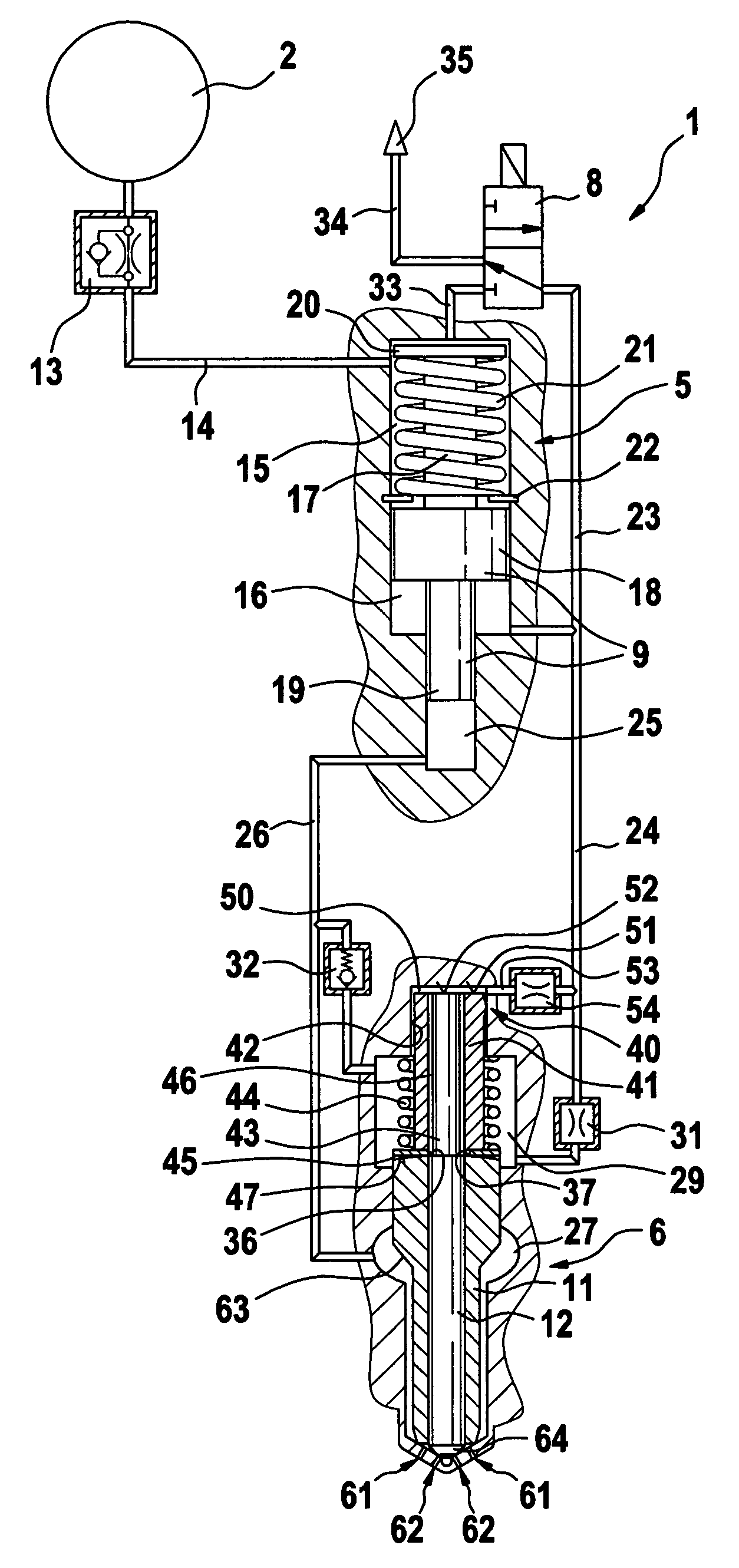
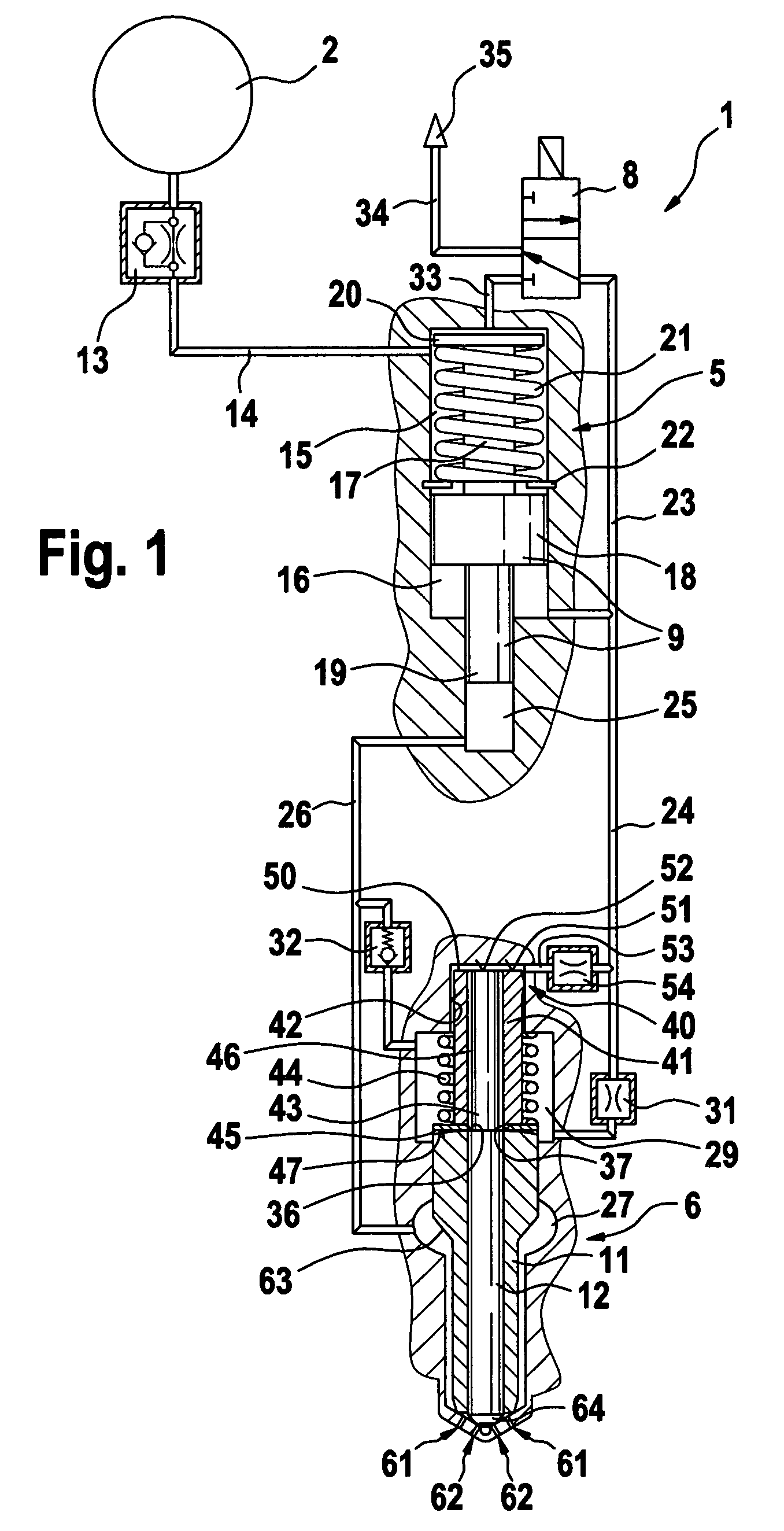
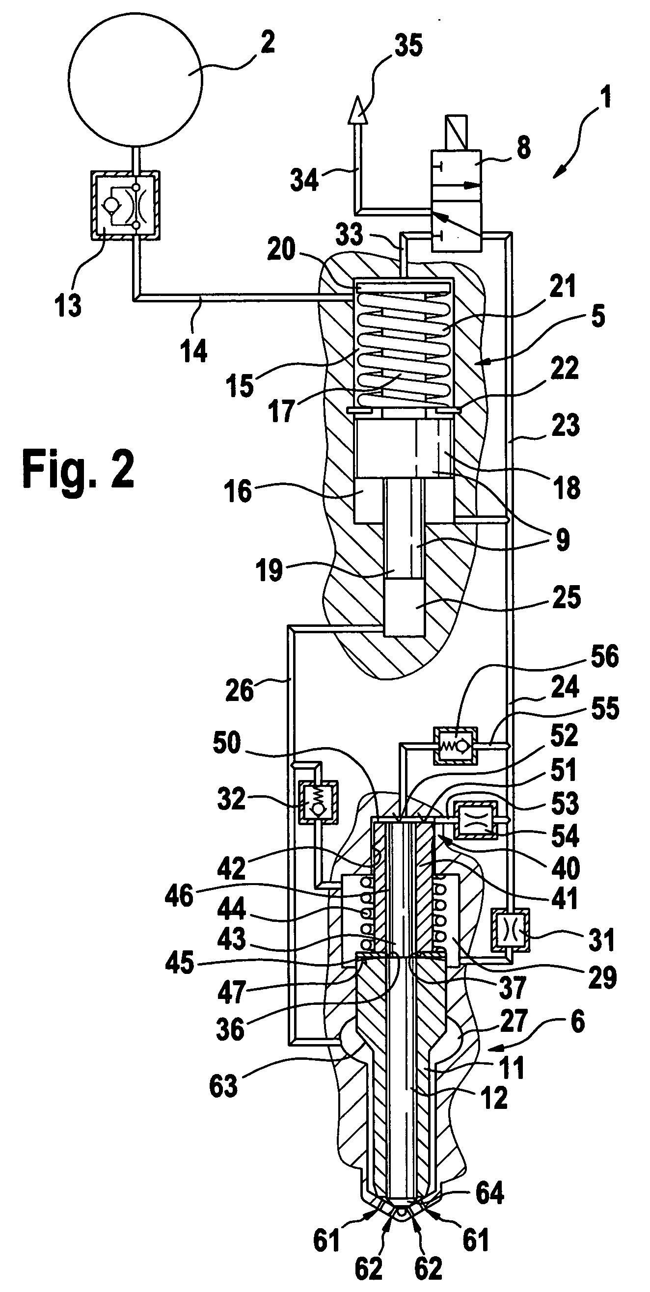
[0020] The fuel injection system shown in FIGS. 1 through 6 includes a fuel injector 1 and a high-pressure reservoir 2 (common rail); the fuel injector 1 is supplied with fuel that is at high pressure via the common rail 2. The fuel injector 1 includes a pressure booster 5, a control valve 8, and an injection valve 6, by way of which injection valve, fuel is injected into a combustion chamber, not shown, of an internal combustion engine, on the end toward the combustion chamber. The control valve 8, embodied for instance as a 3 / 2-way valve, is actuated by an electromagnet, in the exemplary embodiments described herein. However, it is also possible to actuate the control valve 8 by means of a piezoelectric actuator.

[0021] The injection valve 6 has a coaxial nozzle needle, with an outer nozzle needle 11 and an inner nozzle needle 12. The nozzle needles 11, 12 are guided, resting one inside the other, and are actuatable independently of one another. The injection valve 6 furthermore h...


PUM


Abstract

A fuel injection system for internal combustion engines with a fuel injector that can be supplied from a high-pressure fuel source has an injection valve, with injection nozzles pointing toward the combustion chamber, and coaxial inner and outer nozzle needles assigned to the injection nozzles are triggerable as a function of pressure to open and close various injection cross sections at the injection nozzles. Each of the nozzle needless is assigned a respective damping piston, and the damping pistons are movable relative to one another and act on a damping chamber which can be made to communicate with a low-pressure return system via an outlet throttle. In addition to the damping chamber, a closing chamber is provided, to which an end face of the outer nozzle needle is exposed in the closing direction. The closing chamber can be made to communicate with the low-pressure return system as well, via a closing chamber throttle; the outlet throttle has a greater throttling action than the closing chamber throttle, so that the pressure in the closing chamber drops first, and only after a delay does the pressure in the damping chamber drop as well.

Description

BACKGROUND OF THE INVENTION [0001] 1. Field of the Invention [0002] The invention relates to an improved fuel injection system for internal combustion engines. [0003] 2. Description of the Prior Art [0004] A fuel injector with two rows of injection nozzles in the form of holes, to each of which an inner nozzle needle and coaxial to it an outer nozzle needle are assigned, is known for instance from German Patent Disclosure DE 102 05 970 A1. Such injection nozzles, which when triggered as a function of pressure open various injection cross sections, are also known as Vario nozzles. The outer and inner nozzle needles are each assigned a respective control piston, and each of these pistons acts on a fuel-filled hydraulic chamber, so that the hydraulic chambers act as actively connected control chambers. The two control chambers communicate hydraulically with one another via a connecting conduit. The control chamber of the outer nozzle needle can be made to communicate with a low-pressur...

Claims


Application Information

Patent Timeline
Patent Type & Authority Applications(United States)
IPC IPC(8): F02M45/08F02M47/02F02M57/02F02M61/20F02M63/00
CPCF02M45/086F02M47/027F02M57/025F02M2200/46F02M61/205F02M2200/304F02M57/026
Inventor BRENK, ACHIMKROPP, MARTIN
Owner ROBERT BOSCH GMBH
Why Eureka
Try Eureka