Fuel injection apparatus for internal combustion engines, with nozzle needles that can be actuated directly

Inactive Publication Date: 2005-10-13
ROBERT BOSCH GMBH
View PDF16 Cites 24 Cited by
  • Summary
  • Abstract
  • Description
  • Claims
  • Application Information

AI Technical Summary

Benefits of technology

[0007] The object of the present invention is to further improve the adaptability of the fuel injection apparatus to

Problems solved by technology

In this connection, manufacturing tolerances

Method used


Image

  • Fuel injection apparatus for internal combustion engines, with nozzle needles that can be actuated directly
  • Fuel injection apparatus for internal combustion engines, with nozzle needles that can be actuated directly
  • Fuel injection apparatus for internal combustion engines, with nozzle needles that can be actuated directly

Examples


Embodiment Construction

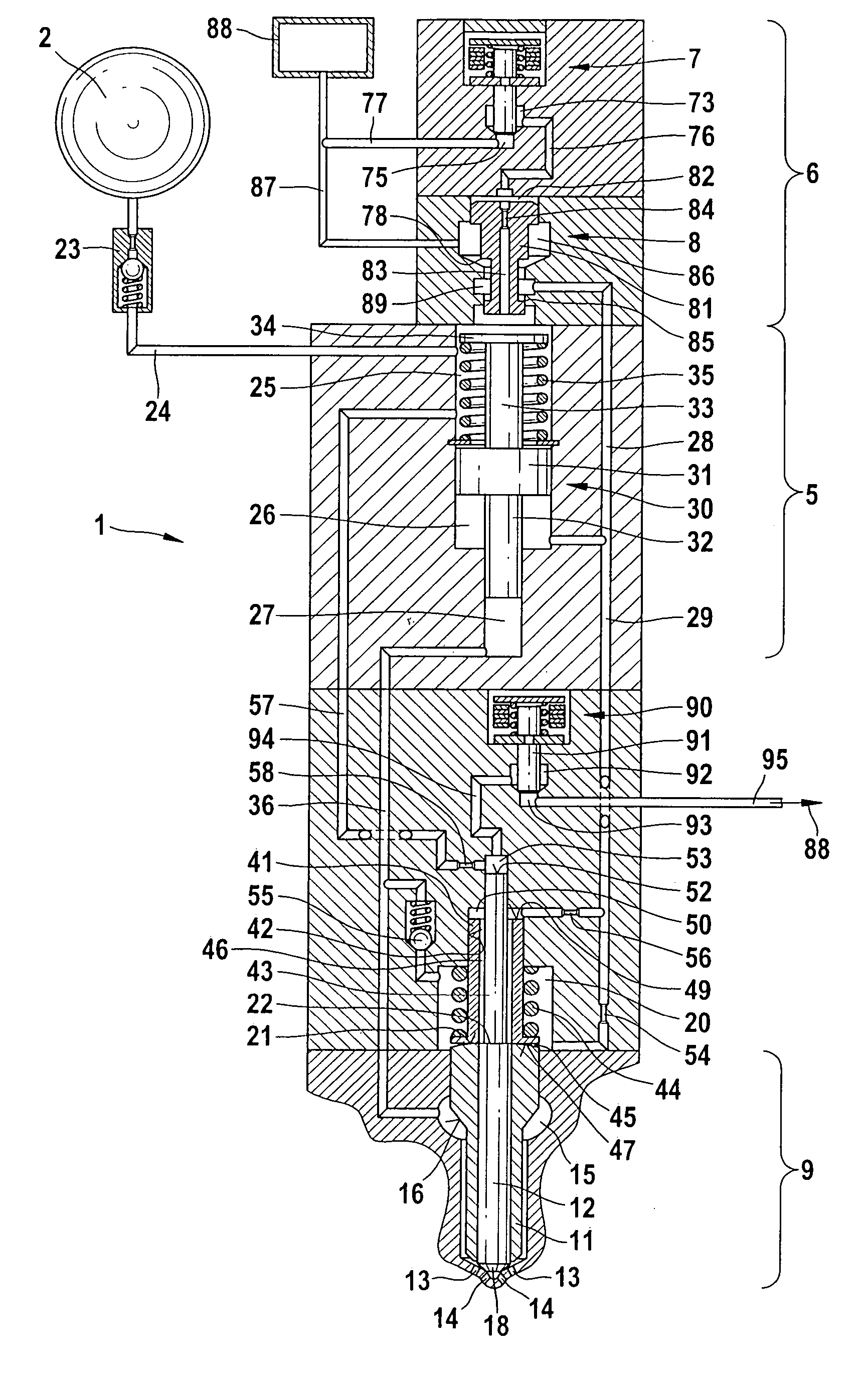
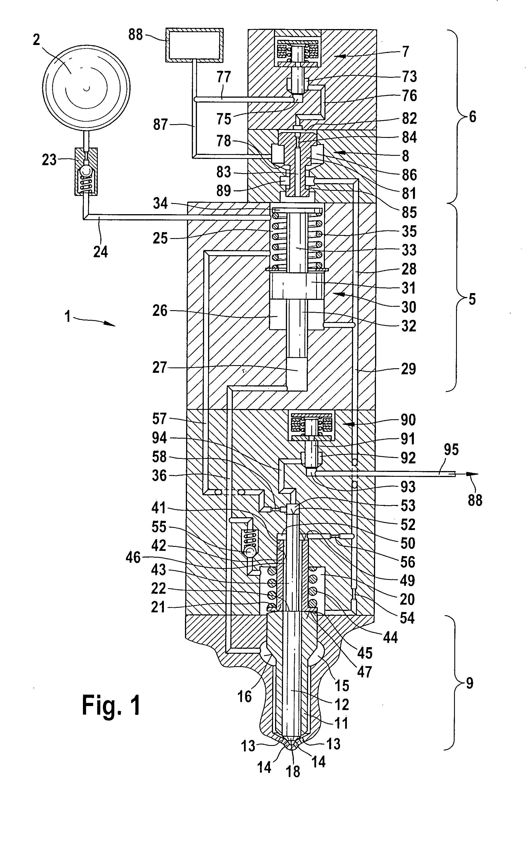
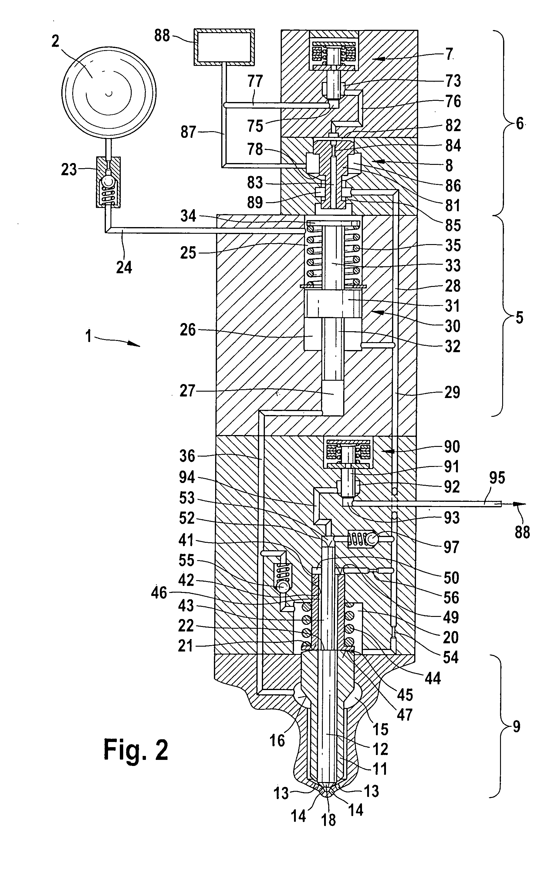
[0018] The fuel injection apparatuses shown in FIGS. 1 through 4 include a fuel injector 1 and a high-pressure accumulator 2 (common rail); the high-pressure accumulator 2 supplies highly pressurized fuel to the fuel injector 1. The fuel injector 1 includes a pressure booster 5, a servo-valve 6, and an injection valve 9 whose combustion chamber end injects fuel into a combustion chamber, not shown, of an internal combustion engine. The servo-valve 6, which is embodied for example in the form of a 3 / 2-way valve, has a first on / off valve 7 and a control valve 8 actuated by it. In the present exemplary embodiment, an electromagnet actuates the on / off valve 7. However, a piezoelectric actuator can also take the place of the electromagnet. In other embodiment forms for the servo-valve 6, it is also possible to use a directly-controlled solenoid valve or a pressure-balanced 3 / 2-way valve with a piezoelectric actuator.

[0019] The injection valve 9 has a vario-nozzle with an outer nozzle ne...


PUM


Abstract

A fuel injection apparatus having a fuel injector fed by a high-pressure fuel source and having an injection valve with injection nozzles associated with coaxial inner and outer nozzle needles can be actuated in a pressure-dependent manner to open and close various injection cross sections at the injection nozzles. A pressure surface of the outer nozzle needle is associated with a closing chamber. To actuate the outer nozzle needle, a first on/off valve can connect the closing chamber to a low-pressure/return system. The inner nozzle needle has a control piston whose pressure surface protrudes into a second control chamber, and a second on/off valve is can connect the control chamber to the low-pressure/return system so that when the second on/off valve is actuated, the pressure is relieved in the second control chamber. This permits a separate actuation of the outer nozzle needle and inner nozzle needle.

Description

BACKGROUND OF THE INVENTION [0001] 1. Field of the Invention [0002] The invention relates to an improved fuel injection apparatus for internal combustion engines. [0003] 2. Description of the Prior Art [0004] A fuel injector, which has two rows of injection nozzle holes that are associated with an inner nozzle needle and an outer nozzle needle that is positioned coaxial to the inner one, is known, for example, from DE 102 05 970 A1. Injection nozzles of this kind, which can be actuated in a pressure-dependent manner to open various injection cross sections, are also referred to as vario-nozzles. The outer and inner nozzle needles are each associated with a control piston that acts on a respective fuel-filled hydraulic chamber so that the hydraulic chambers function as actively operating control chambers. The two control chambers are hydraulically connected to each other via a connecting conduit. The control chamber of the outer nozzle needle can be connected to a low-pressure return...

Claims


Application Information

Patent Timeline
IPC IPC(8): F02M45/00F02M45/08F02M47/02F02M57/02F02M59/10F02M61/18F02M63/00
CPCF02M45/086F02M47/027F02M57/025F02M59/105F02M61/1806F02M63/0015F02M63/0026F02M63/0029F02M63/004F02M63/0043F02M63/0045F02M2200/46
Inventor BRENK, ACHIMKROPP, MARTINMAGEL, HANS-CHRISTOPH
Owner ROBERT BOSCH GMBH
Why Eureka
Try Eureka