Boosted fuel injector with rapid pressure reduction at end of injection

a fuel injector and pressure reduction technology, which is applied in the direction of fuel injection apparatus, machine/engine, feed system, etc., can solve the problems of reducing the requisite tolerance, difficult to meet the requirements of mass production, and difficult to achieve the requisite tolerances at present in mass production, so as to improve the emissions value of the exhaust gas, reduce the diameter, and accelerate the depressurization

Inactive Publication Date: 2005-05-17
ROBERT BOSCH GMBH
View PDF10 Cites 23 Cited by
  • Summary
  • Abstract
  • Description
  • Claims
  • Application Information

AI Technical Summary

Benefits of technology

[0012]The present invention avoids not only the use of a control valve embodied as a 3 / 2-way valve but also the disadvantages associated with the use of a 2 / 2-way valve with a filling throttle or fill valve, or in other words a pressure drop that proceeds only slowly toward the end of the injection. With the embodiment proposed according to the invention, the filling throttle and the fill valve are replaced by a pressure relief valve, but by way of it a very fast depressurization can be achieved at the end of an injection event. The fast depressurization (rapid spill) at the end of the injection phase in turn considerably improves the emissions values of the exhaust gas of self-igniting internal combustion engines.
[0013]The pressure relief valve is integrated with the control line for relieving the control chamber of the pressure booster. The valve body of the pressure relief valve can not only be embodied as a cylindrical body but can also include a region which can be embodied with a reduced diameter, for instance in the form of a constriction. The face ends of the valve body of the pressure relief valve can not only have equal hydraulically effective surface areas but also different diameters. In the pressure relief valve, two opposed hydraulic chambers can be embodied that communicate with one another through a through bore in the valve body of the pressure relief valve. The flow cross section of the through bore inside the valve body of the pressure relief valve is selected such that a pressure difference builds up between the hydraulic chambers of the pressure relief valve, so that the pressure relief valve can be kept closed.
[0014]By using a metering valve embodied as a 2 / 2-way valve, the use of a 3 / 2-way valve, which can be produced only in a complex way because of the requisite tolerance and is therefore expensive, can be avoided. Using a pressure relief valve in the control line of the pressure booster makes a fast pressure drop possible at the end of the injection, and as a result fast closure of an injection valve member, embodied for instance as a nozzle needle, can be achieved.

Problems solved by technology

For reasons of strength, the attainable pressure level in storage injection systems used at present is currently limited to about 1600 bar.
In terms of production technology, however, a 3 / 2-way valve is very complicated to produce and is thus expensive.
The requisite tolerances cannot be mastered at present in mass production.
When a fill valve is employed, however, a slow pressure drop results at the end of injection, down to the pressure level prevailing in the high-pressure storage chamber, which leads to poor emissions.
Moreover, a depressurization that proceeds only slowly toward the end of an injection phase has the disadvantage that the mean injection pressure level is decreased considerably.

Method used


Image

  • Boosted fuel injector with rapid pressure reduction at end of injection
  • Boosted fuel injector with rapid pressure reduction at end of injection
  • Boosted fuel injector with rapid pressure reduction at end of injection

Examples


Embodiment Construction

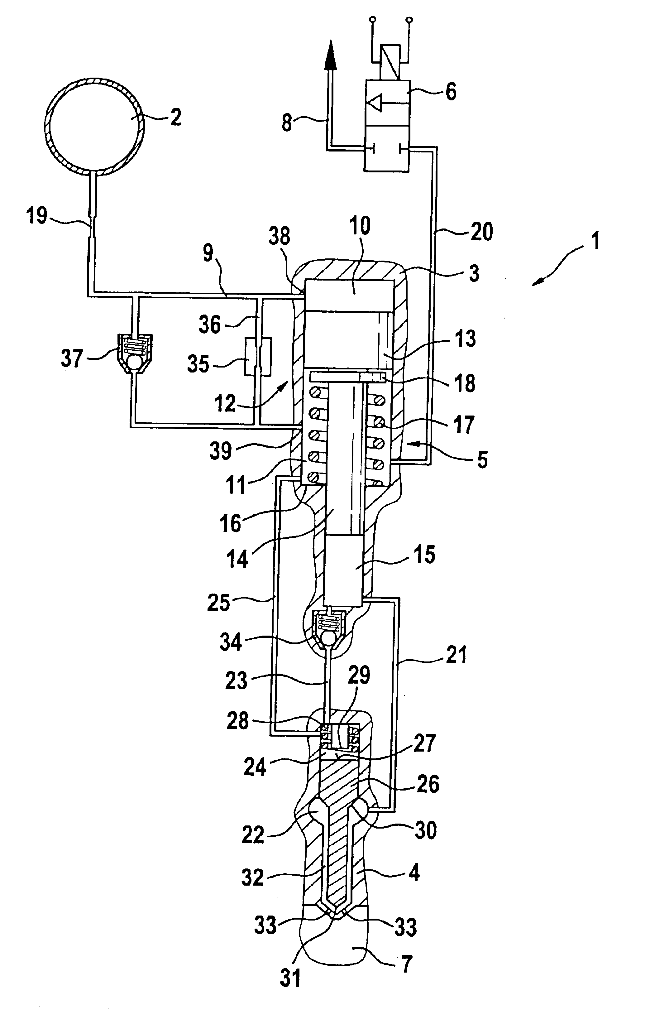
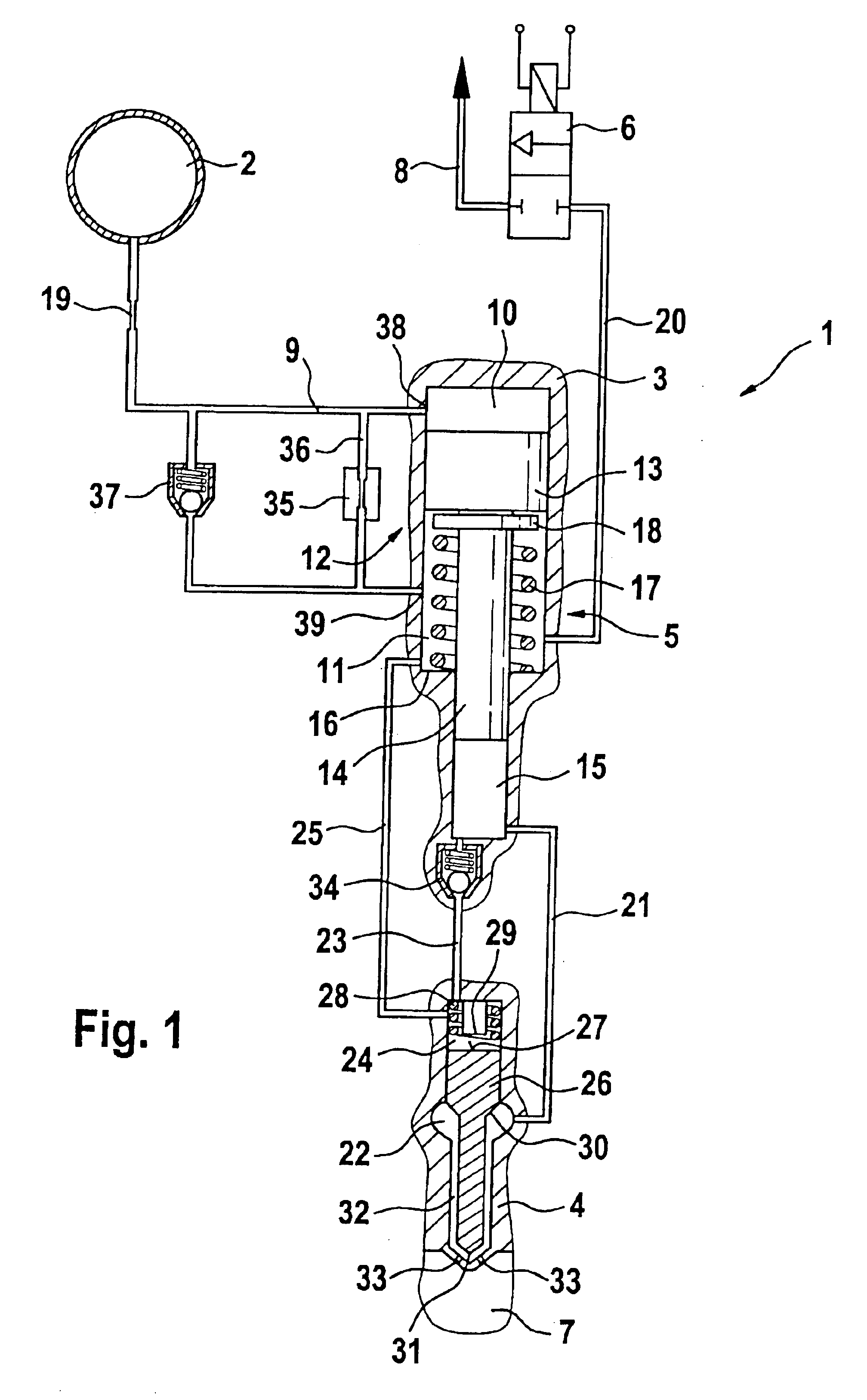
[0021]FIG. 1 shows a prior art pressure-boosted fuel injector, with a parallel-connected fill valve and filling throttle, that has a slow depressurization behavior.

[0022]The fuel injection system shown in FIG. 1 includes a fuel injector 1 and a high-pressure storage chamber 2 (common rail). The fuel injector 1 includes an injector body 3, a nozzle body 4, with a pressure booster 5 received in the injector body 3, and a metering valve 6, which in the arrangement shown in FIG. 1 is embodied as a 2 / 2-way valve. By means of the fuel injector 1, fuel at high pressure is injected into a combustion chamber 7 of a self-igniting internal combustion engine.

[0023]From the metering valve 6, a low-pressure-side return 8 extends into a fuel container, not shown, such as the fuel tank of a motor vehicle.

[0024]From the high-pressure storage chamber 2 (common rail), fuel at high pressure flows via a supply line 9 into a work chamber 10 of the pressure booster 5. The pressure booster 5 further includ...


PUM


Abstract

A device for injecting fuel into the combustion chamber of an internal combustion engine including a high-pressure storage chamber, a pressure booster, and a metering valve. The pressure booster includes a work chamber and a control chamber separated from one another by an axially movable piston. A pressure change in the control chamber causes a pressure change in a compression chamber of the pressure booster. The compression chamber acts upon a nozzle chamber in the nozzle body. A pressure relief valve (40) is in a control line between the control chamber of the pressure booster and a 2 / 2-way metering valve, the pressure relief valve includes a valve body that acts upon at least one hydraulic chamber and can be made to communicate with the pressure prevailing in the high-pressure storage chamber.

Description

CROSS-REFERENCE TO RELATED APPLICATIONS[0001]This application is a 35 USC 371 application of PCT / DE 03 / 01098 filed on Apr. 3, 2003.BACKGROUND OF THE INVENTION[0002]1. Field of the Invention[0003]Both pressure-controlled and stroke-controlled injection system are known for supplying combustion chambers of self-igniting internal combustion engines with fuel. As fuel injection systems, not only unit fuel injectors but also pump-line-nozzle units and storage injection systems are used. Storage injection systems (common rail injection systems) advantageously make it possible to adapt the injection pressure to the load and rpm of the engine. To achieve high specific outputs and to reduce emissions from the engine, the highest possible injection pressure is generally necessary.[0004]2. Prior Art[0005]For reasons of strength, the attainable pressure level in storage injection systems used at present is currently limited to about 1600 bar. To further increase the pressure in storage injectio...

Claims


Application Information

Patent Timeline
Patent Type & Authority Patents(United States)
IPC IPC(8): F02M57/00F02M57/02F02M59/00F02M59/10F02M47/02F02M45/00F02M47/00F02M61/10
CPCF02M45/00F02M47/027F02M59/105F02M57/026F02M57/025
Inventor MAGEL, HANS-CHRISTOPH
Owner ROBERT BOSCH GMBH
Why Eureka
Try Eureka