Vehicle brake control device

a brake control and vehicle technology, applied in the direction of brake systems, process and machine control, instruments, etc., can solve the problems of slowing down the depressurization of the w/c, unable to achieve sufficiently quick depressurization, and obstacles

Inactive Publication Date: 2007-09-06
ADVICS CO LTD
View PDF8 Cites 7 Cited by
  • Summary
  • Abstract
  • Description
  • Claims
  • Application Information

AI Technical Summary

Benefits of technology

[0008]It is therefore an object of the present invention to provide a vehicle brake control device which controls W / C pressures of wheels of a vehicle by means of linear valves and achieves quick depressurization of the linear valves required to achieve a proper ABS control.
[0010]Thus, the vehicle brake control device cuts off one or more of the first to fourth linear valves in order to prohibit completely supply of the current to the one or more of the first to fourth linear valves, in the case that a slip ratio corresponding to the one or more of the first to fourth liner valves is larger than the first threshold. Thus, it is possible to avoid slow depressurization of one or more of the W / C pressures caused by a weak current. In other words, it is possible to achieve quick response in one or more of the W / C pressures which allows the depressurization to work well.
[0014]Thus, in supplying again the currents to one or more of the first to fourth linear valves after cutting off the current, the current value to one or more of the first to fourth linear valves is adjusted based on the W / C pressures detected by one or more of the pressure sensors. Thus, it is possible to find the current value corresponding to the differential pressures generated by the first to fourth linear valves. In this way, it is possible to make the current to be supplied to the linear valves quickly regain the current values matching the differential pressures being generated at the linear valves.

Problems solved by technology

However, the inventors of the present invention have found that depressurizing of the W / Cs cannot be sufficiently quick if the vehicle brake control device performs nothing more than changing the indication values to decrease the W / C pressures in the ABS control.
The weak current slows down the depressurization of the W / C and therefore obstacles sufficiently quick depressurization of the linear differential pressure valves.

Method used


Image

  • Vehicle brake control device
  • Vehicle brake control device
  • Vehicle brake control device

Examples


first embodiment

[0028]A vehicle brake control device according to a first embodiment of the present invention is applied to a vehicle with an X-shaped hydraulic circuit including two conduit systems, one of which serves the right front wheel and the left rear wheel and the other of which serves the left front wheel and the right rear wheel.

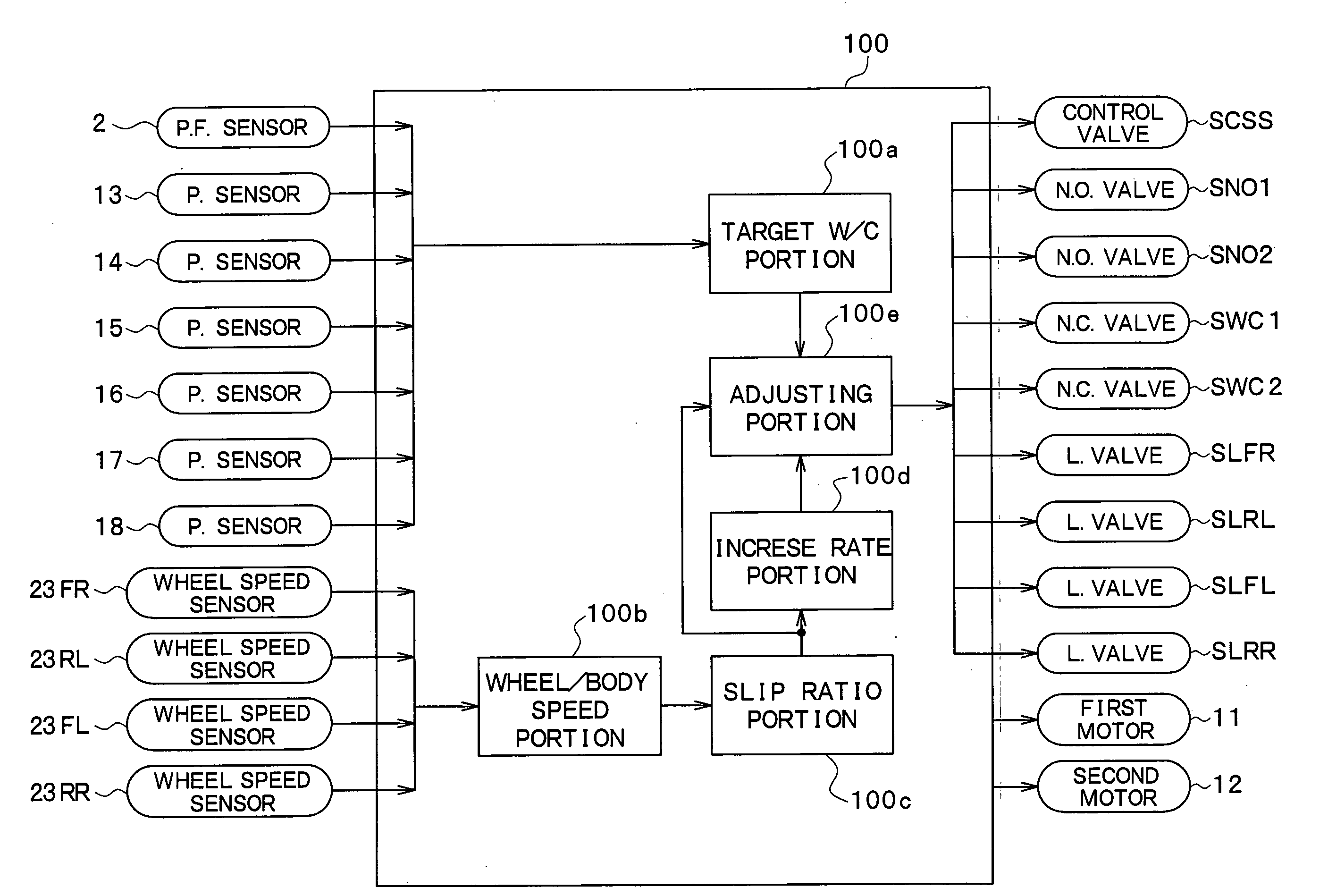
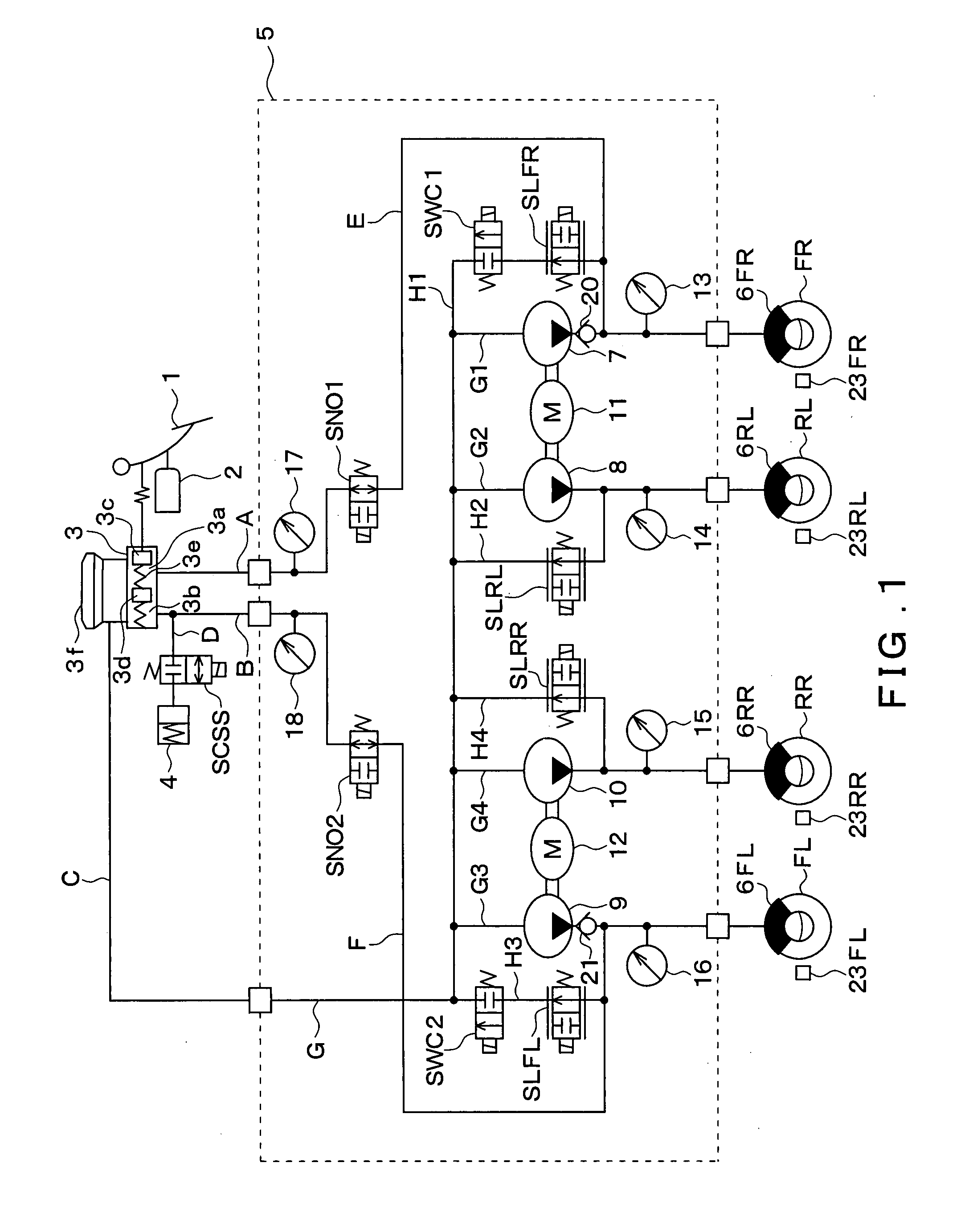
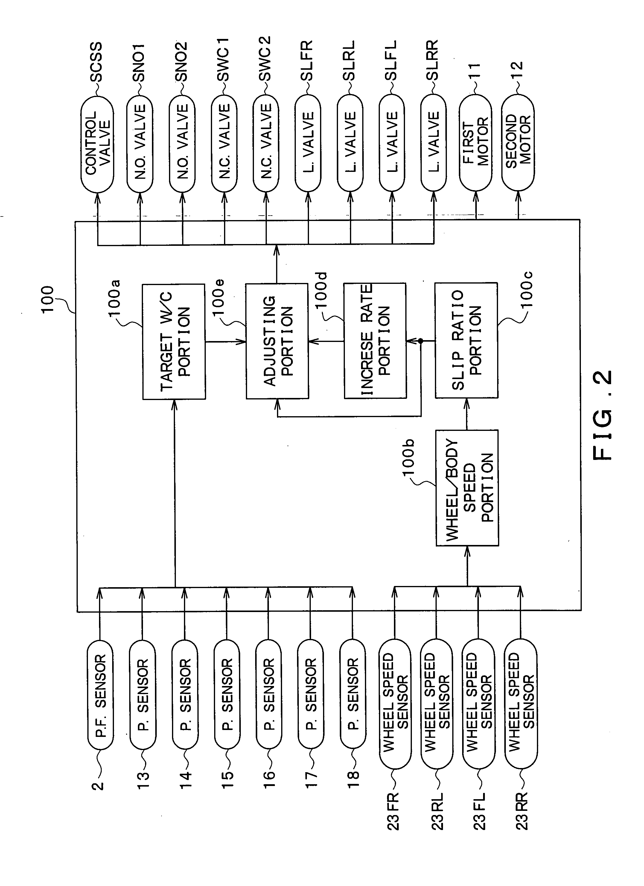
[0029]As shown in FIG. 1, the vehicle brake control device includes a brake pedal 1, a depression force sensor 2, a master cylinder (hereinafter referred to as an M / C) 3, a stroke control valve SCSS, a stroke simulator 4, a brake fluid pressure control actuator 5, and wheel cylinders (hereinafter referred to as W / Cs) 6FL, 6FR, 6RL, 6RR, as well as a brake ECU 100 shown in FIG. 2.

[0030]When the brake pedal 1, which is an example of a brake operating member, is depressed by a driver, the depression force applied to the brake pedal 1 is inputted to the depression force sensor 2, and a detection signal corresponding to the applied depression force is outputted by the...

second embodiment

[0100]A second embodiment of the present invention will be described. In this embodiment, a portion of the configuration of the vehicle brake control device is different from the configuration in the first embodiment, but the overall configuration is basically the same as that in the first embodiment, so only the parts which are different from the first embodiment will be described.

[0101]FIG. 6 is a diagram showing a hydraulic circuit configuration of a vehicle brake control device according to this embodiment. As shown in FIG. 6, in the vehicle brake control device in this embodiment, the brake conduit G is divided into two brake conduits Ga and Gb. The first normally-closed valve SWC1 is located in the brake conduit Ga (that is, downstream of the dividing point of the conduits Ga and Gb and upstream of the brake conduits H1 and H2). The second normally-closed valve SWC2 is located in the brake conduit Gb (that is, downstream of the dividing point and upstream of the brake conduits...

third embodiments

[0106]Third embodiment of the present invention will be described. In this embodiment, a portion of the configuration of the vehicle brake control device is different from the configuration in the second embodiment, but the overall configuration is basically the same as that in the second embodiment, so only the parts which are different from the second embodiment will be described.

[0107]FIG. 7 is a diagram showing a hydraulic circuit configuration of a vehicle brake control device according to this embodiment. As shown in FIG. 7, in the vehicle brake control device in this embodiment, the two conduit systems share a single normally-closed valve SWC, instead of the first and second normally-closed valves SWC1 and SWC2 provided in the first and second embodiments.

[0108]The vehicle control device with the structure described above achieves the same effect as that of the first and second embodiments if it cuts off one or more of the first to fourth linear valves SLFR, SLRL, SLFL, and S...


PUM


Abstract

A vehicle brake control device cuts off one or more of the first to fourth linear valves in order to prohibit completely supply of a current to the one or more of the first to fourth linear valves, in the case that a slip ratio of one or more wheels is larger than a first threshold. Thus, it is possible to avoid slow depressurization of the W / C pressure caused by the weak current. In other words, it is possible to achieve quick response in the W / C pressures which allows the depressurization to work well.

Description

CROSS REFERENCE TO RELATED APPLICATION[0001]This application is based on and incorporates herein by reference Japanese patent application No. 2006-59422 filed on Mar. 6, 2006.FIELD OF THE INVENTION[0002]The present invention relates to a vehicle brake control device which generates pressures (hereinafter referred to as W / C pressures) in wheel cylinders (hereinafter referred to as W / Cs) by causing pumps to apply pressures.BACKGROUND OF THE INVENTION[0003]A conventional vehicle brake control device is proposed in Japanese Patent Publication No. H11-301435 which drives pumps by means of motors and generates W / C pressures at W / Cs for respective wheels by causing the pump to draw in and discharge brake fluid.[0004]In the conventional vehicle brake control device, linear differential pressure valves are provided in conduit systems respectively connecting discharge ports of the pumps with a reservoir for supplying brake fluid. The W / C pressures are controlled by means of the linear differe...

Claims


Application Information

Patent Timeline
Patent Type & Authority Applications(United States)
IPC IPC(8): G06G7/76
CPCB60T8/17616B60T13/161B60T8/4081B60T8/3655
Inventor MAKI, KAZUYANIINO, HIROAKI
Owner ADVICS CO LTD
Why Eureka
Try Eureka