Method for joining members, and joint body
a joint body and member technology, applied in the direction of fastening means, vehicle components, transportation and packaging, etc., can solve the problems of moldability degradation, increased molding load, size accuracy degradation, etc., and achieve the effect of reducing deformation burden, high joint strength, and high joining strength
- Summary
- Abstract
- Description
- Claims
- Application Information
AI Technical Summary
Benefits of technology
Problems solved by technology
Method used
Image
Examples
first embodiment
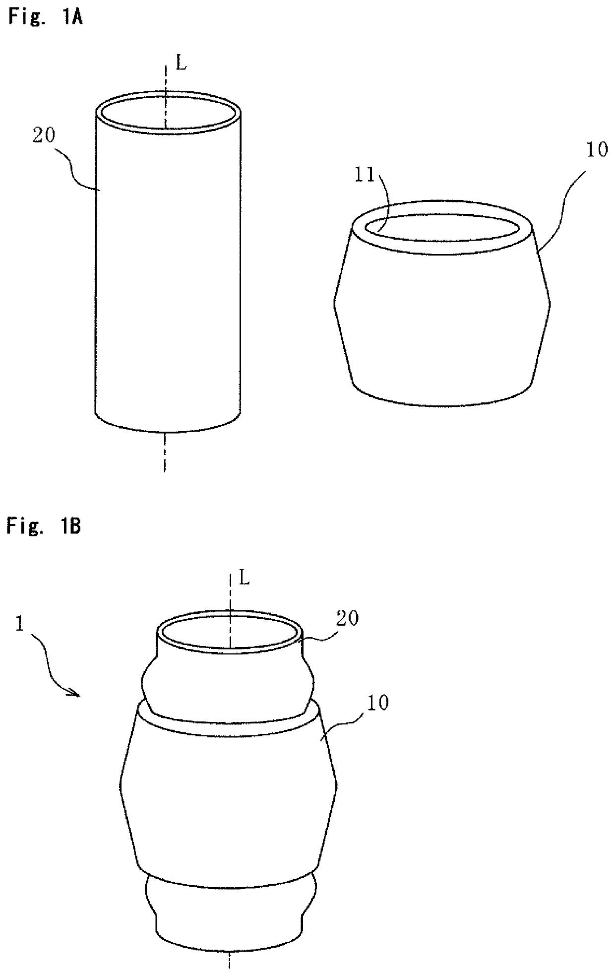
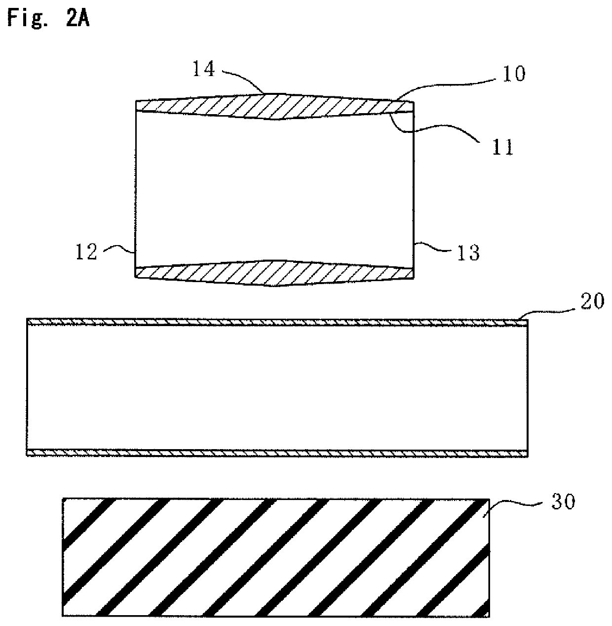
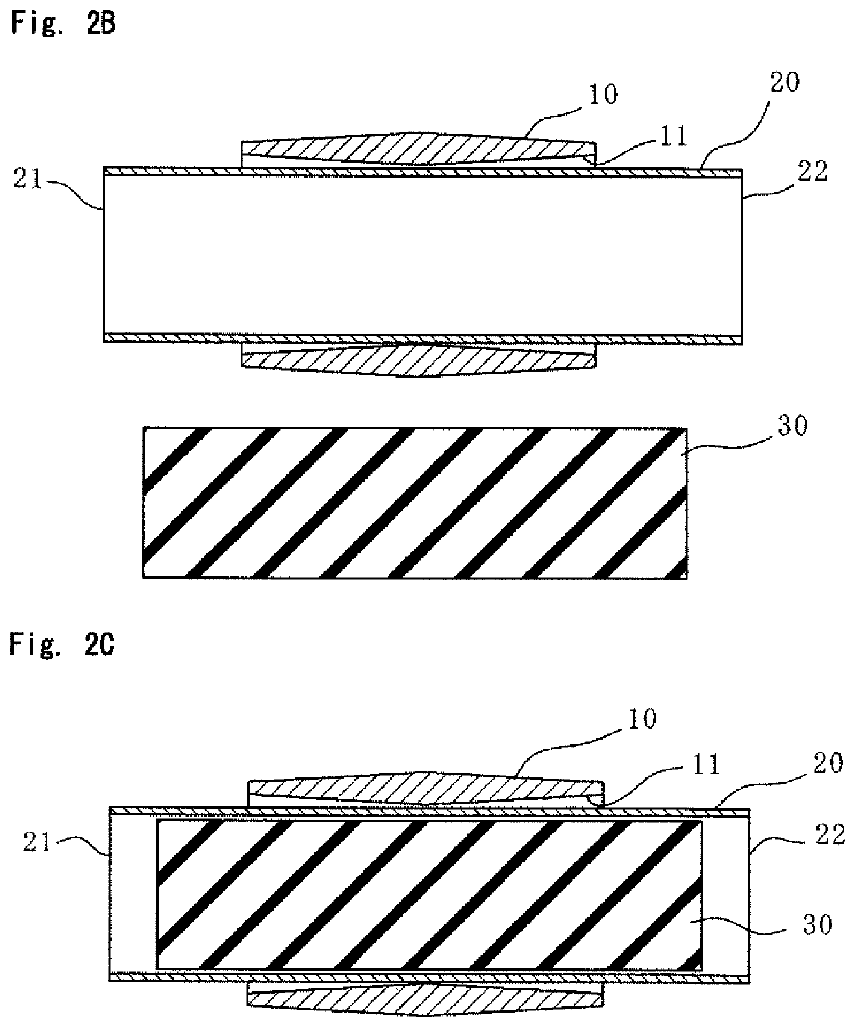
[0046]With reference to FIGS. 1A to 2D, there will be described a method for joining members for joining a wall surface body (first member) 10 and a tubular body (second member) 20 to each other by press-fitting.
[0047]As illustrated in FIG. 1A, the wall surface body 10 is a circular pipe with a hole portion 11 with a circular cross section. The wall surface body 10 is a die-molded article fabricated through die casting and is formed from an aluminum alloy, a magnesium alloy, a zinc alloy, or a copper alloy, for example. Since the wall surface body 10 is a die-casted article, the wall surface body 10 is provided with a draft angle in its hole portion 11. The draft angle is provided from the opposite end portions 12 and 13 toward the center portion 14, namely in different directions, rather than being provided in a single direction from one end portion 12 toward the other end portion 13 (see FIG. 2A). More specifically, the draft angle is provided such that the hole diameter decreases...
second embodiment
[0060]FIGS. 4A and 4B illustrate a method for joining members according to a second embodiment. In the present embodiment, the same constituent elements as those in the first embodiment will be designated by the same reference characters and will not be described redundantly.
[0061]In the present embodiment, a core 44 is used unlike in the first embodiment. The core 44 is a steel component with a circular cylindrical shape, for example. The shape and the material of the core 44 are arbitrary, provided that the core 44 is not deformed by the compressing force from the pressurizing apparatus 40.
[0062]As illustrated in FIG. 4A, in the present embodiment, in a process corresponding to the third process in the first embodiment, the core 44 is inserted into the inside of the tubular body 20, similarly to elastic bodies 30. When the elastic bodies 30 are inserted into the tubular body 20, they are inserted thereinto in the opposite sides with the core 44 sandwiched therebetween. That is, in...
third embodiment
[0065]FIGS. 5A to 6B illustrate a method for joining members according to a third embodiment. In the present embodiment, the same constituent elements as those in the first embodiment will be designated by the same reference characters and will not be described redundantly.
[0066]In the present embodiment, unlike in the first embodiment, the wall surface body 10 and the tubular body 20 have respective substantially-trapezoid cross sections. The wall surface body 10 includes an upper wall 15, a lower wall 16 which faces the upper wall 15 and has a larger length than that of the upper wall 15, and two side walls 17 coupling these walls to each other. The upper wall 15 in the wall surface body 10 is provided with an uninclined surface 18 with no draft angle in its inner surface, and the lower wall 16 is provided with an opening portion 19 at the position facing the uninclined surface 18. Therefore, the tubular body 20 is exposed from the wall surface body 10 through the opening portion ...
PUM
| Property | Measurement | Unit |
|---|---|---|
| draft angles | aaaaa | aaaaa |
| draft angle | aaaaa | aaaaa |
| draft angle | aaaaa | aaaaa |
Abstract
Description
Claims
Application Information
 - R&D
- Intellectual Property
- Life Sciences
- Materials
- Tech Scout
- Unparalleled Data Quality
- Higher Quality Content
- 60% Fewer Hallucinations
Browse by: Latest US Patents, China's latest patents, Technical Efficacy Thesaurus, Application Domain, Technology Topic, Popular Technical Reports.
© 2025 PatSnap. All rights reserved.Legal|Privacy policy|Modern Slavery Act Transparency Statement|Sitemap|About US| Contact US: help@patsnap.com


