
Illuminating device

a technology of illumination device and illumination chamber, which is applied in the direction of lighting and heating apparatus, semiconductor devices for light sources, instruments, etc., can solve the problems of poor plant growth, inability to control the growth of plants uniformly, and inconvenient natural growth appearance of plants

Active Publication Date: 2021-07-06
VEELED
View PDF7 Cites 0 Cited by
  • Summary
  • Abstract
  • Description
  • Claims
  • Application Information

AI Technical Summary

Benefits of technology

The device achieves uniform illumination across the plant, promoting healthy growth by maintaining high light intensity at the periphery and center, effectively addressing the issue of uneven light distribution and reducing the need for multiple light sources.

Problems solved by technology

However, in most cases, based on changes in the weather of nature, or changes in the growth environment of plants, there are still situations in which plants cannot receive the sunlight in nature for a long time, so as to make the plants growing poor.
However, the natural growth appearance of plants is not completely consistent.
Therefore, under a single light source, light intensities of light receiving areas are different, which cannot control the plants growing uniformly.
Although there are people who use multiple light sources, which needs considerable space and the construction cost is too expansive.

Method used


Image

  • Illuminating device
  • Illuminating device
  • Illuminating device

Examples


Embodiment Construction

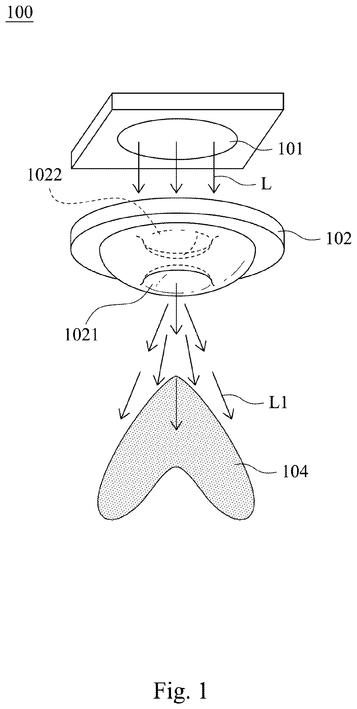
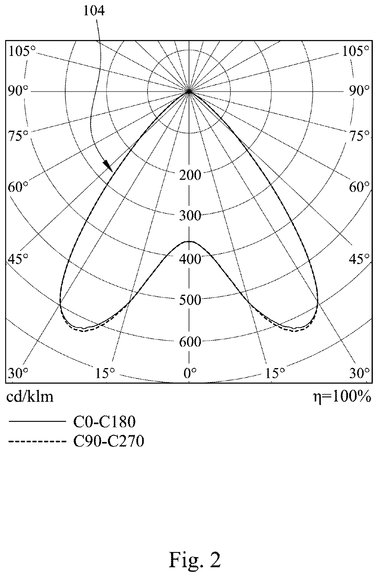
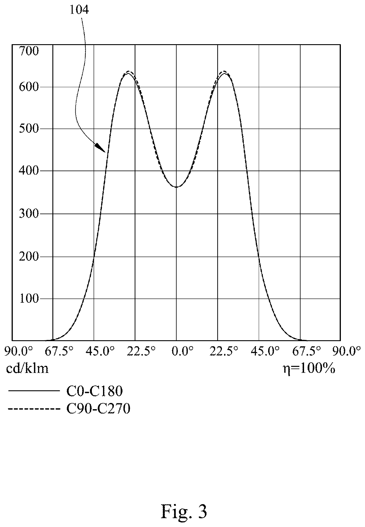
[0020]FIG. 1 is a structural schematic view of an illuminating device 100 according to one embodiment of the present disclosure. FIG. 2 is a light-pattern 104 schematic view of the illuminating device 100 according to the embodiment of FIG. 1. FIG. 3 is another light-pattern 104 schematic view of the illuminating device 100 according to the embodiment of FIG. 1. The illuminating device 100 includes a light source 101 and a light-pattern generating member 102. The light source 101 emits an incident light L. The light-pattern generating member 102 is disposed on a side of the light source 101 to receive the incident light L. The incident light L passes through the light-pattern generating member 102 so as to generate a transmission light L1. The transmission light L1 generates a light pattern 104, wherein the transmission light L1 at the peripheral portion of the light pattern 104 has a high light intensity relative to the transmission light L1 at other portions of the light pattern 1...


PUM

PropertyMeasurementUnit
microstructuresaaaaaaaaaa
light intensity distributionaaaaaaaaaa
light intensityaaaaaaaaaa

Abstract

An illuminating device includes a light source and a light-pattern generating member. The light source emits an incident light. The light-pattern generating member is disposed on a side of the light source to receive the incident light. The incident light passes through the light-pattern generating member so as to generate a transmission light. The transmission light generates a light pattern. A light intensity distribution is formed by the light pattern, and a light intensity near the light source is equal to a light intensity far from the light source.

Description

RELATED APPLICATIONS[0001]This application claims priority to Taiwan Application Serial Number 108200080, filed Jan. 3, 2019, which is herein incorporated by reference.BACKGROUNDTechnical Field[0002]The present disclosure relates to an illuminating device. More particularly, the present disclosure relates to an illuminating device capable of generating a plurality of transmission lights with different light intensities via a light-pattern generating member, so as to provide a uniform illumination according to the irregular shape of plants or pots.Description of Related Art[0003]In the general nature, the sunlight can almost provide a broad spectrum covering the ultraviolet region, the visible region and the infrared region. There are studies have proven that illuminating plants will affect plants growing. For example, the purple-light wave of the purple light region can inhibit the growth hormone in the plant, make the plant grow into a short thick shape, and also affect the phototr...

Claims


Application Information

Patent Timeline
Patent Type & Authority Patents(United States)
IPC IPC(8): F21V5/04A01G7/04G02B27/09F21Y115/10F21Y115/15
CPCF21V5/04A01G7/045G02B27/0916G02B27/0955F21V5/046F21V5/048F21Y2115/10F21Y2115/15F21V5/005F21V9/00
Inventor YU, HENRY
Owner VEELED
Learn More