
Control device and control method for lock-up clutch

a control device and lock-up clutch technology, which is applied in the direction of fluid gearings, transportation, and gearings, can solve the problems of fuel consumption deterioration, and achieve the effect of avoiding the release of the lock-up clutch and avoiding fuel consumption deterioration

Active Publication Date: 2021-07-20
JATCO LTD
View PDF12 Cites 2 Cited by
  • Summary
  • Abstract
  • Description
  • Claims
  • Application Information

AI Technical Summary

Benefits of technology

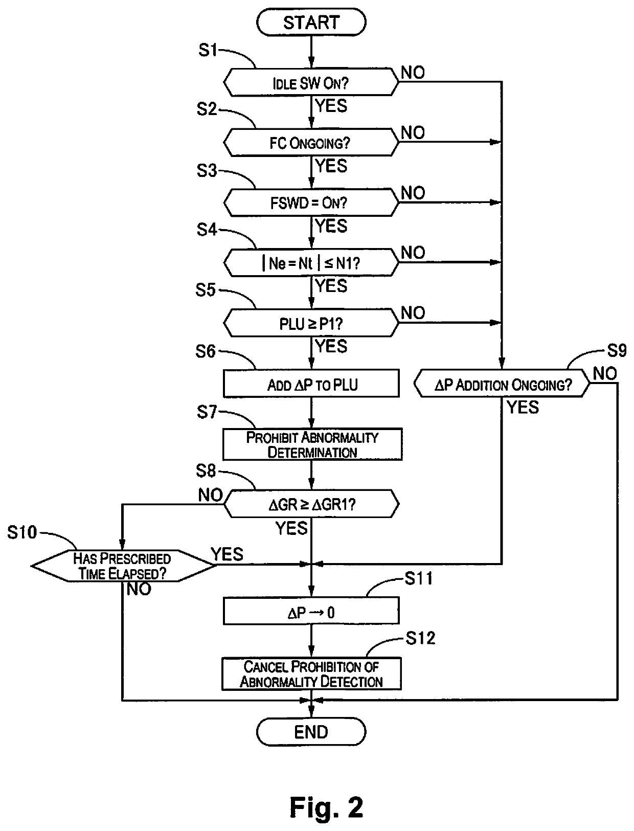
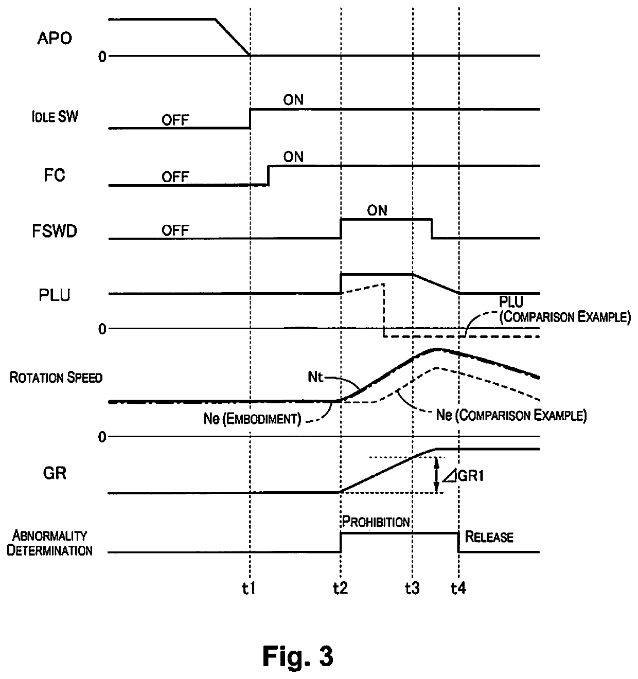
[0007]Thus, it is possible to avoid releasing of the lock-up clutch due to an abnormality determination, and by maintaining the engine rotation speed at higher than the idle rotation speed, it is possible to suppress the engine independent operation section that accompanies fuel injection, and possible to avoid deterioration of fuel consumption.

Problems solved by technology

Having done that, it is necessary to restart fuel injection to rotate independently, and there was the problem that fuel consumption deteriorated.

Method used


Image

  • Control device and control method for lock-up clutch
  • Control device and control method for lock-up clutch
  • Control device and control method for lock-up clutch

Examples


Embodiment Construction

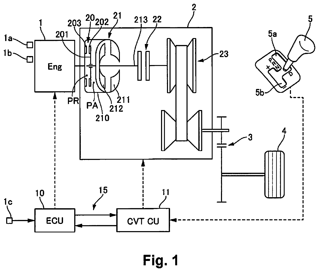
[0011]FIG. 1 is a system diagram of a vehicle to which the control device for a lock-up clutch of this embodiment is applied. The rotation that is output from an engine 1, which is an internal combustion engine, is input to an automatic transmission 2. The rotation that is input to the automatic transmission 2 is input to a belt type continuously variable transmission mechanism 23 via a torque converter 21 and a clutch 22 provided with a lock-up clutch 20.

[0012]The torque converter 21 has: a converter cover 210 connected to an engine output shaft; a pump impeller 211 attached to the converter cover 210; and a turbine runner 212 placed at a position facing opposite the pump impeller 211. The turbine runner 212 rotates as an integrated unit with a turbine shaft 213 connected with the engine side rotation elements of the clutch 22.

[0013]The lock-up clutch 20 has: a friction material 203 provided on the engine side inner wall of the converter cover 210; a clutch plate 201 that is slidea...


PUM


Abstract

A control device for a lock-up clutch includes a control unit, an abnormality determination unit, a release control unit and a prohibition unit. The control unit is configured to control an engagement state of a lock-up clutch, and to perform a slip lock-up control by performing a feedback control of an engagement hydraulic pressure to be a first slip amount during coasting. The abnormality determination unit is configured to determine an abnormality when a state continues with a slip amount being equal to or greater than a second slip amount. The release control unit is configured to release the lock-up clutch when the abnormality is determined. The prohibition unit is configured to allow the control unit to raise the engagement hydraulic pressure by a prescribed pressure, and to prohibit determination by the abnormality determination unit, when the transmission ratio is downshifted during coasting while the slip lock-up control is performed.

Description

CROSS-REFERENCE TO RELATED APPLICATIONS[0001]This is a U.S. national phase application of PCT / JP2018 / 003149, filed on Jan. 31, 2018, which claims priority to Japanese Patent Application No. 2017-015836, filed on Jan. 31, 2017. The entire disclosure of Japanese Patent Application No. 2017-015836 is hereby incorporated herein by reference.TECHNICAL FIELD[0002]The present invention relates to a control device and a control method for a lock-up clutch that controls the engagement state of a lock-up clutch provided with a torque converter.BACKGROUND ART[0003]In Japanese Patent Publication No. S62-7430, disclosed is a technique for releasing a lock-up clutch when the state of the slip amount being a fixed level or greater continues to be a fixed time or greater when doing feedback control of the slip amount of the lock-up clutch.[0004]Here, during coasting, by an automatic transmission shifting to the low side, and the turbine rotation speed rising, despite being normal, the slip amount o...

Claims


Application Information

Patent Timeline
Patent Type & Authority Patents(United States)
IPC IPC(8): F16H61/14F16D48/06F16H61/12F16H45/02F16H59/38F16H59/46F16H59/72
CPCF16H61/14F16D48/066F16H61/12F16H2045/0294F16H2059/385F16H2059/467F16H2059/725F16D48/06F16D2500/10487F16D2500/30406F16D2500/30806F16D2500/5085F16D2500/5102F16D2500/70406F16D2500/7105F16H61/143F16H2061/1232F16H2061/1276F16H2061/145F16H2061/147Y02T10/60F16H2061/0015F16H2061/1256
Inventor IIZUMI, TAKEHIRONODA, TOSHIAKIYAMADA, TAKAHIROKOGUCHI, TAKASHIISHIYAMA, YUICHI
Owner JATCO LTD
Learn More