Chair

a technology for chairs and backrests, applied in the field of chairs, can solve the problems of inability to move into a supported forward sitting position, inconvenient use, complex and costly solutions for connected chairs, etc., and achieve the effects of convenient use, low cost, and simple structur

Active Publication Date: 2021-07-27
DESANTA SIMON
View PDF24 Cites 0 Cited by
  • Summary
  • Abstract
  • Description
  • Claims
  • Application Information

AI Technical Summary

Benefits of technology

[0005]Hence it is a task of the present invention to develop a chair which, despite a comparatively simple, inexpensive design, offers a high degree of ergonomy and comfort and is suitable for use as a connected chair in particular, or other similar purposes. This chair should, in particular, be equally comfortable and easy to use for persons of different body weights and should also provide a supported forward sitting position of the type described above.

Problems solved by technology

Lighter persons are therefore scarcely able to make use of the motion mechanism of the chair with associated comfort.
They cannot, however, be moved into a supported forward sitting position in which the seat back is tilted forward out of the unsolicited position and also supports the person sitting on the chair in a forward-oriented sitting position.
From a mechanical point of view, appropriate solutions are too complex and costly for connected chairs and have thus far only been used for office chairs and swivel chairs.
The constructions used for this purpose are relatively complex and costly, and are therefore difficult to transfer to connected chairs.

Method used


Image

  • Chair
  • Chair
  • Chair

Examples


first embodiment

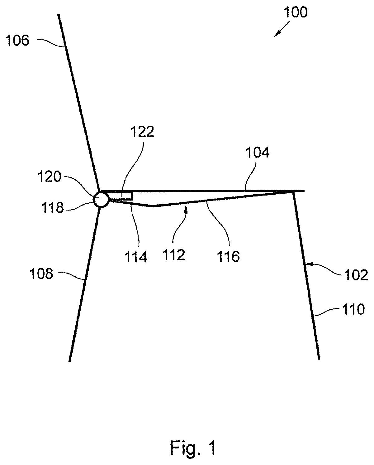
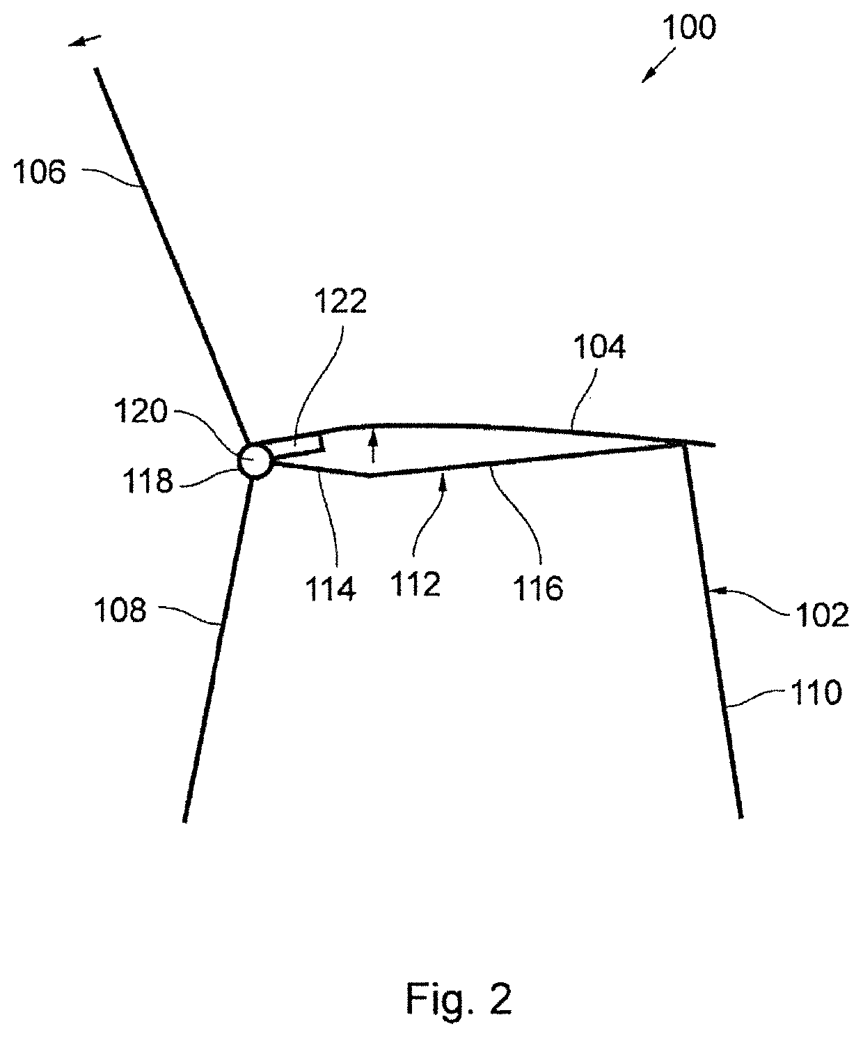
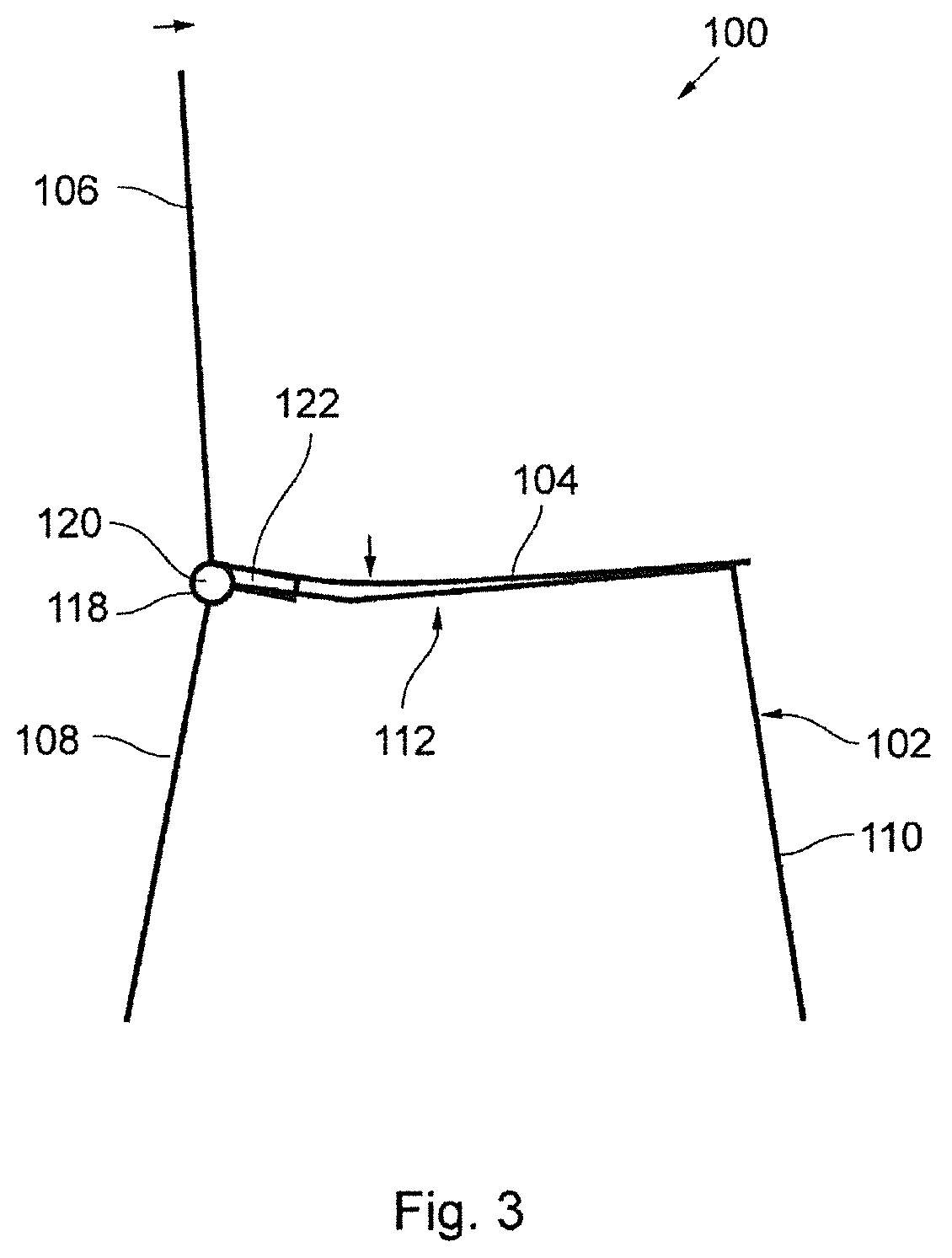
[0047]Chair 100 according of the first embodiment can be designed as a stackable chair or further developed into such a chair. In this respect, the details shown in FIGS. 1 to 3 should not be considered limiting for the present Invention to the effect that they stand in the way of such stackability. Furthermore, the mechanism according to the invention Is not associated solely with stackable chairs, but may also be used with other underframe constructions, e.g. for office chairs with a swivel frame.

[0048]The following FIGS. 4 to 15 show a second embodiment of chair 10 according to the invention. Like the chair 100 shown in FIGS. 1 to 3, chair 10 according to the second embodiment comprises an underframe 12, a seat section 14 and a seat back 16. As usual, seat section 14 is essentially horizontal and disposed on underframe 12 such that it slopes only slightly towards the rear, i.e. towards seat back 16.

[0049]Seat back 16 is inclined slightly backwards with respect to the vertical pos...

second embodiment

[0052]From the bottom end of seat back 16 a pair of levers extends underneath seat section 14 from the rear. In the present second embodiment of chair 10, these levers form the supporting element for supporting seat section 14. In the side views in FIGS. 4 to 6 only one lever 28 is visible, which will be referred to in the following description. Lever 28 (and its counterpart on the opposite side of chair 10) may for example be rigidly attached to transverse axis 26, which rotates together with seat back 16 inside bearing 24. Lever 28 therefore follows the pivot movement of seat back 16. If seat back 16 is tilted backward, the front end of lever 28 rises and exerts pressure on seat section 14 from below.

[0053]Seat section 14 is essentially divided into two parts in the crosswise direction, namely a longer front part 30 and a shorter rear part 32. Front part 30 is connected with rear part 32 by a film hinge 34 whose hinge axis lies approximately in the top side, i.e. in the actual sea...


PUM


Abstract

Chair (10, 100) with a seat section (14, 104), an underframe (12, 102) which supports seat section (14), and a seat back (16, 106), in which the seat back (16, 106) is mounted on underframe (12, 102) such that it may be pivoted around a rear transverse axis (26, 120) oriented crosswise to chair (10, 100), and seat section (14, 104) is at least partially deformable and is supported or reinforced by at least one stiff supporting element (28, 122) extending from the bottom end of seat back (16, 106) in the direction of seat section (14, 104) and being rigidly connected with seat back (16, 106), such that when a pivoting movement of seat back (16, 106) occurs, a portion of seat section (14, 104) positioned in front of the end of supporting element (28, 122) is raised or lowered depending on the direction of pivoting.

Description

BACKGROUND OF THE INVENTION[0001]The present invention concerns a chair with a seat section, an underframe which supports the seat section and a seat back.[0002]As is known, chairs come in a wide variety of designs. In the simplest design, the seat back is rigidly attached to the seat section which is in turn supported by an underframe with four legs. Chairs used for seating in halls and event rooms frequently come with side elements for lateral connection with an adjacent chair. Furthermore, such chairs for sitting in rows are usefully designed to be stacked to allow space-saving storage. A connected chair of this type is disclosed in WO 2008 / 064886 for example.[0003]To enhance comfort and ergonomy, it is desirable that the chair is able to adapt to a certain extent to the weight of the person sitting on it. When solicited, the seat back should give a little yet still provide sufficient support to the user. The seat section may also be of a resiliently pliant design and connected t...

Claims


Application Information

Patent Timeline
Patent Type & Authority Patents(United States)
IPC IPC(8): A47C1/032A47C1/02A47C1/023A47C3/04
CPCA47C1/03261A47C3/045A47C3/04
Inventor DESANTA, SIMON
Owner DESANTA SIMON
Why Eureka
Try Eureka