Optical element for lighting device

a technology of optical elements and lighting devices, applied in the field of optical elements, can solve the problems of complex determination of the shape of each optical element, and achieve the effects of improving reflectivity, small lateral dimension, and improving reflectivity

Active Publication Date: 2021-08-03
LUMILEDS
View PDF9 Cites 0 Cited by
  • Summary
  • Abstract
  • Description
  • Claims
  • Application Information

AI Technical Summary

Benefits of technology

[0011]It is an object of the present invention to provide an optical element in particular suitable as precollimator in a lighting device wherein the intensity distribution of the precollimated light is configurable and wherein the shape of the optical element may be easily determined for various dimensions of the optical element. The invention further relates to a lighting device with an improved light intensity distribution as well as to a method for producing a lighting device.
[0040]In another exemplary embodiment according to the invention, the lighting device is configured for automotive lighting, in particular as automotive headlight. Further, a use of the optical element according to the first aspect as precollimator in automotive lighting, in particular in automotive headlights, is disclosed. As already noted above, embodiments of the optical element are particularly useful to provide an intensity distribution at the light outcoupling surface with high intensities at the second point or the line of second points, such that the illumination of the lighting device may be controlled in a simple manner. In particular, embodiments of the optical element providing a “cut-off” of intensity near the edge of the light outcoupling surface may be advantageous for the use in low-beam headlights.

Problems solved by technology

As lighting devices such as automotive headlights may comprise an arrangement of multiple light-emitting elements and various shapes of collimators, determining a suitable shape for each optical element may be intricate.

Method used


Image

  • Optical element for lighting device
  • Optical element for lighting device
  • Optical element for lighting device

Examples


Embodiment Construction

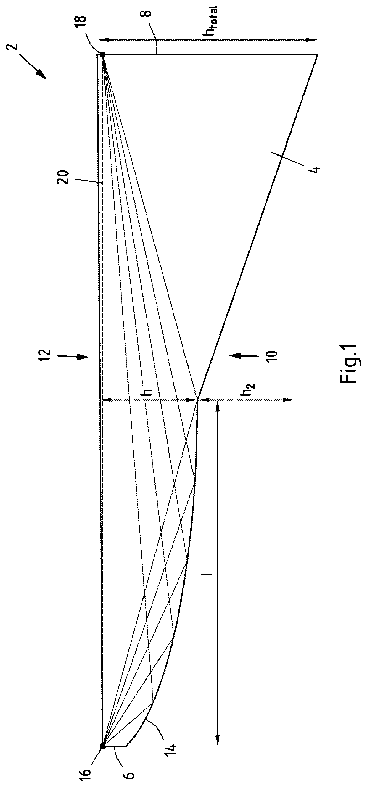
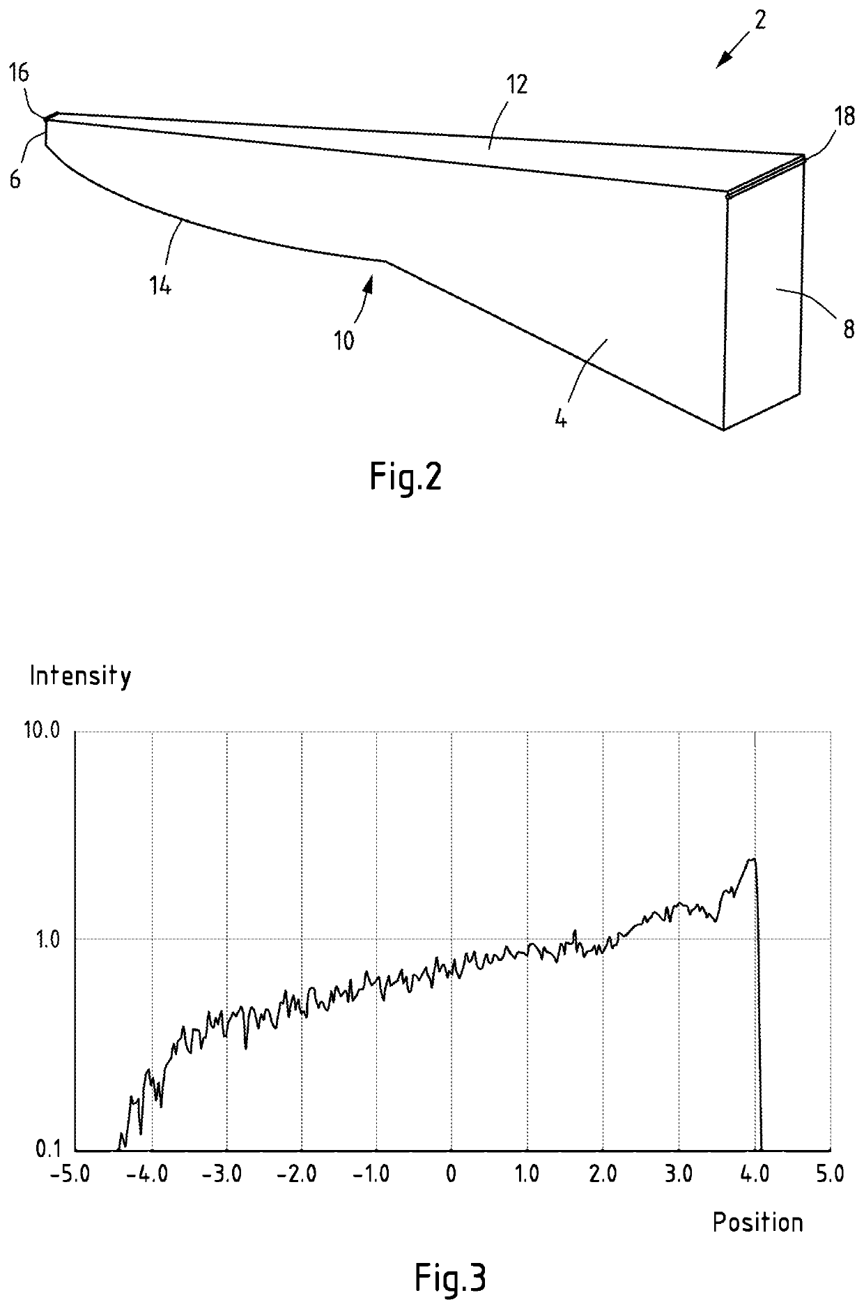
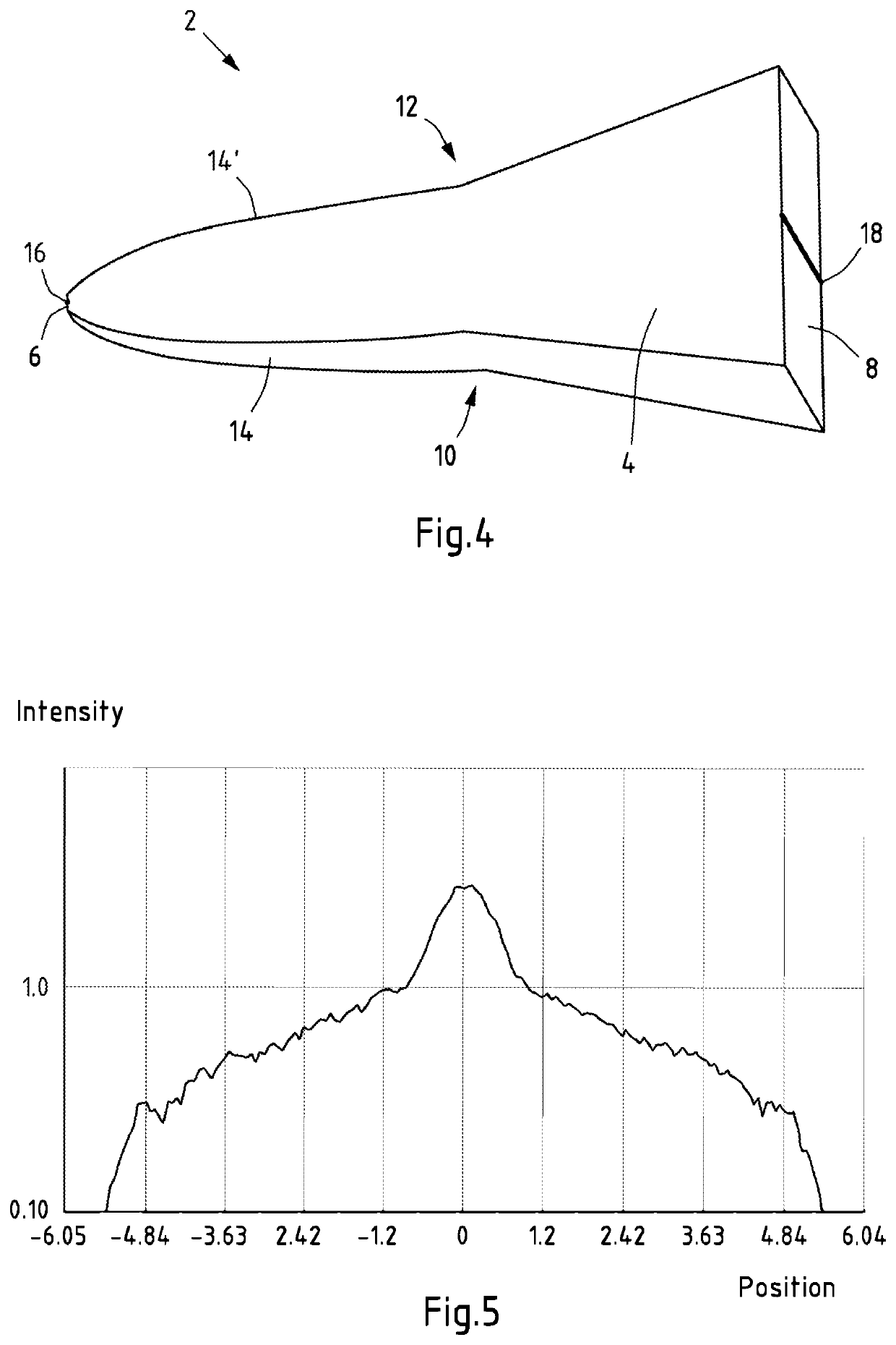
[0051]FIG. 1 shows a schematic representation of a first embodiment of an optical element 2 for a lighting device in a cross-sectional view. The optical element 2 comprises a body 4 capable of conducting light, for instance a body 4 made of transparent silicone.

[0052]The body 4 comprises a light incoupling surface 6 at a first end of the body 4 for coupling to a light-emitting element. The body 4 further comprises a light outcoupling surface 8 at a second end of the body 4 opposite the first end, as well as side faces 10, 12 extending from the light incoupling surface 6 to the light outcoupling surface 8. When a light-emitting element is coupled to the light incoupling surface 6, the optical element 2 may act as (pre-)collimator in that light is conducted and internally reflected by the body 4, while the light may exit from the body at the light outcoupling surface 8 with a specific shape and intensity distribution.

[0053]The side face 10 has an aspherical shape 14 in the section sho...


PUM

PropertyMeasurementUnit
lengthaaaaaaaaaa
lengthaaaaaaaaaa
” anglesaaaaaaaaaa

Abstract

The disclosure relates to an optical element for a lighting device, the optical element comprising a body capable of conducting light, wherein the body comprises: a light incoupling surface; a light outcoupling surface; and side faces situated opposite to each other and extending from the light incoupling surface to the light outcoupling surface; wherein at least one of the side faces has an aspherical shape at least in sections. The at least one side face having the aspherical shape is capable of focussing light originating from a first point on the light incoupling surface to a second point on the light outcoupling surface by internal reflection at least in the sections. The optical element may serve in the lighting device as a precollimator with configurable intensity distribution of the precollimated light. The shape of the optical element may be easily determined for various dimensions of the optical element. The disclosure further relates to a lighting device and a method for production of a lighting device.

Description

CROSS REFERENCE TO RELATED APPLICATIONS[0001]This application claims priority to European Patent Application No. 18198285.1 filed on Oct. 2, 2018 titled “OPTICAL ELEMENT FOR LIGHTING DEVICE.” European Patent Application No. 18198285.1 is incorporated herein by reference.FIELD OF THE INVENTION[0002]The present disclosure relates to optical elements for use in lighting devices, in particular as precollimators in lighting devices comprising light-emitting elements such as light-emitting diodes (LEDs).BACKGROUND OF THE INVENTION[0003]Lighting devices may comprise collimators configured to shape a beam of light for illumination from the light emitted by a light source. For example, a beam of substantially parallel light with specific dimensions may be obtained from the light emitted by a light source by means of a collimator. Collimators may for instance comprise reflective elements and / or refractive and / or diffractive elements, e.g. reflective cups and / or lenses.[0004]For applications s...

Claims


Application Information

Patent Timeline
Patent Type & Authority Patents(United States)
IPC IPC(8): G02B27/09F21S41/24F21S41/32G02B27/30F21Y115/10F21S41/151
CPCG02B27/0927F21S41/24F21S41/322G02B27/30F21S41/151F21Y2115/10F21S41/143F21S41/25F21S41/285
Inventor ZOZGORNIK, STEFFEN
Owner LUMILEDS
Why Eureka
Try Eureka