Phase-type zone plate photon sieve

A technology of photon sieve and zone plate, applied in the field of phase zone plate photon sieve

Active Publication Date: 2011-06-15
INST OF MICROELECTRONICS CHINESE ACAD OF SCI
View PDF0 Cites 0 Cited by
  • Summary
  • Abstract
  • Description
  • Claims
  • Application Information

AI Technical Summary

Problems solved by technology

It can focus and image X-rays, which cannot be achieved by general prisms and imaging optics made of glass materials.

Method used


Image

  • Phase-type zone plate photon sieve
  • Phase-type zone plate photon sieve
  • Phase-type zone plate photon sieve

Examples


Embodiment Construction

[0028] In order to make the objectives, technical solutions and advantages of the present invention more clearly understood, the present invention will be further described in detail below with reference to specific embodiments and accompanying drawings.

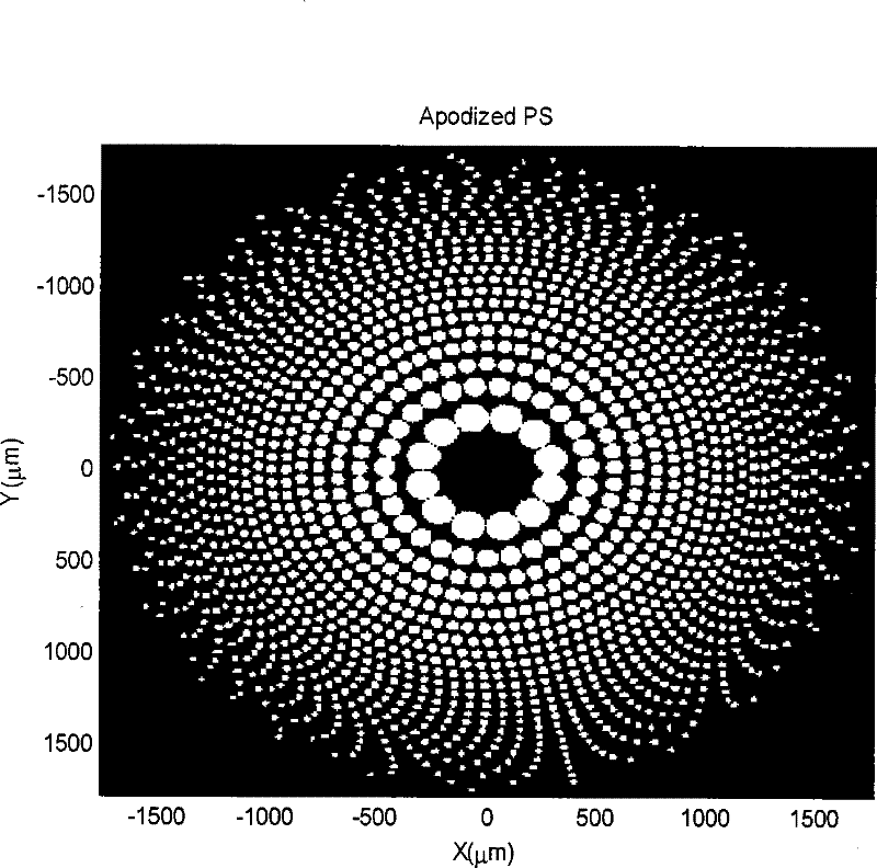
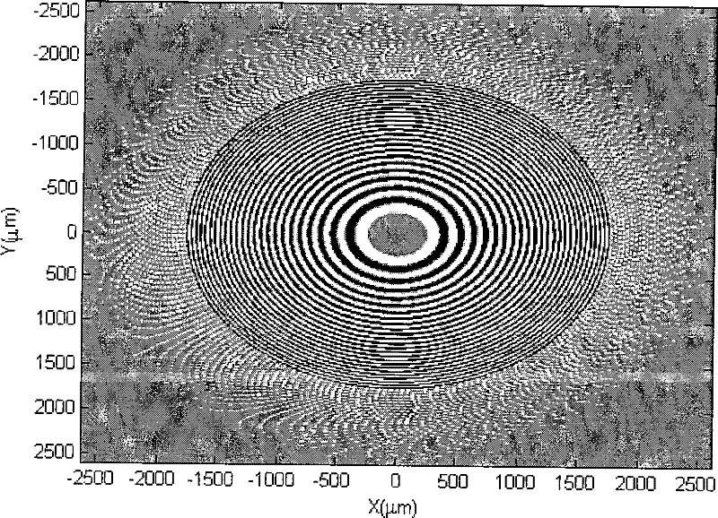
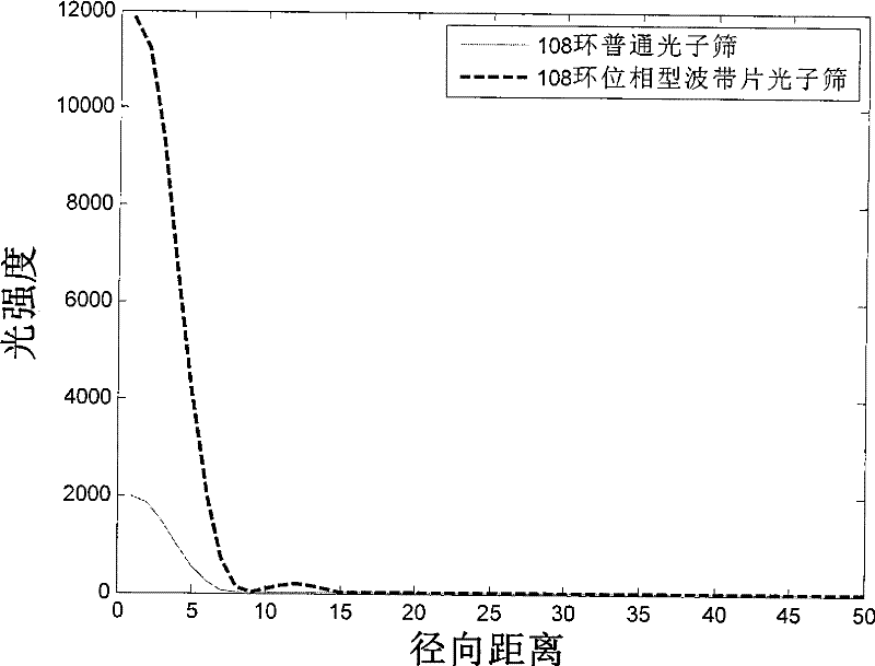
[0029] Phase-type zone plate photonic sieve is a new type of diffractive optical element. The device is placed before or after the diffraction-limited lens, and corrects the spectral light intensity of the far-field diffraction spot of the laser beam at all levels, so as to realize the diffraction center diffraction spot with more concentrated diffraction center spot energy than the diffraction center spot of the ordinary photon sieve.

[0030] The phase-type zone plate photonic sieve provided by the invention adopts the smaller diffraction circular hole and the diffraction ring structure to replace the single circular diffraction aperture of the ordinary photonic sieve. The present invention provides the design structure of...


PUM


Abstract

The invention discloses a phase-type zone plate photon sieve. The photon sieve consists of a phase Fresnel zone plate circular ring arranged in the center and a photon sieve circular hole arranged around the circular ring, wherein both the circular ring and the photon sieve circular hole are made on transparent medium; a phase Fresnel zone plate is made on the transparent medium firstly and then a photon sieve is made around the phase Fresnel zone plate; and the circular hole of the photon sieve encircles the circular ring of the phase Fresnel zone plate. The phase-type zone plate photon sieve is characterized in that the diameter of a pore on the outmost ring of the photon sieve is coincident with the zone width of the outmost ring of the phase Fresnel zone plate, and both the diameter and the zone width are limited by the minimum linewidth of micromachining; and the zone plate on which the photon sieve is based during making and the phase Fresnel zone plate encircled inside the zone plate have identical parameters, and the diameter of each circular hole is 1.5 times that of the width of a corresponding zone. The phase-type zone plate photon sieve increases the focusing diffraction light intensity of the photon sieve, namely, increasing the energy of the main spot of laser beam far-field diffraction spots.

Description

technical field [0001] The invention belongs to the technical field of laser beam wavefront shaping, in particular to a phase-type zone plate photonic sieve used for realizing the energy enhancement of the laser beam in the far-field diffraction light spot of the main spot. This photonic sieve can be used in beam shaping, maskless etching of microelectronics, intensive laser energy concentration, x-ray focusing and other instruments that require energy to be focused into a central spot. Background technique [0002] It is a practical task to increase the energy of the main laser spot and suppress the energy of the side spots through various approaches. Very small main spot widths and extremely high main spot energies are required in beam shaping, microelectronic maskless etching, intense laser energy concentration, x-ray focusing, and other instruments that require energy to be focused into a central spot. [0003] The phase modulation technology is a technology that realiz...

Claims


Application Information

Patent Timeline
Patent Type & Authority Patents(China)
IPC IPC(8): G03F7/20G21K1/00
Inventor 贾佳谢长青刘明
Owner INST OF MICROELECTRONICS CHINESE ACAD OF SCI
Why Eureka
Try Eureka