Unmanned air vehicle
a technology of unmanned aircraft and propeller, which is applied in the direction of loudspeakers, instruments, transportation and packaging, etc., can solve the problems of difficult to remove the noise generated by the propeller from the target sound, difficult to properly detect the noise, and wind noise to occur, so as to achieve the effect of suppressing wind nois
- Summary
- Abstract
- Description
- Claims
- Application Information
AI Technical Summary
Benefits of technology
Problems solved by technology
Method used
Image

Examples
embodiments
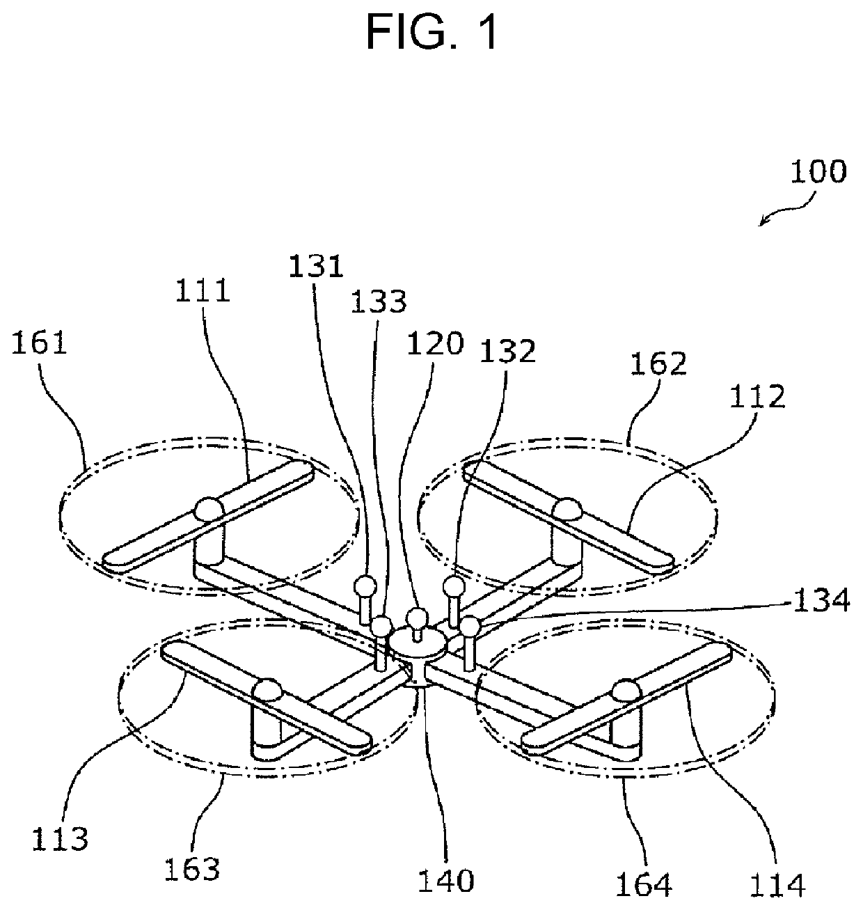
[0062]FIG. 1 is an external view illustrating a structure of an unmanned air vehicle according to an embodiment. In FIG. 1, the unmanned air vehicle 100 includes generators 111 to 114, a main microphone (first microphone) 120, sub-microphones (second microphones) 131 to 134, and a housing 140. The unmanned air vehicle 100 may further include an image capturing apparatus.
[0063]The generators 111 to 114 each generate a force to drive the unmanned air vehicle 100 to fly. For example, the generators 111 to 114 each are a machine including a power source, an actuator that generates a flying force using a motive power transmitted from the power source, and other structural components, and more specifically, for example, each generator includes a motor, one or more rotary wings, and a duct or a guard that surrounds the one or more rotary wings. More specifically, the generators 111 to 114 individually generate forces. The force to drive the unmanned air vehicle 100 to fly includes a plural...
first modification
[0115]In the embodiment described above, the unmanned air vehicle 100 includes the four generators 111 to 114. In contrast, in a first modification described below, the unmanned air vehicle includes one generator.
[0116]FIG. 4 is a cross-sectional view illustrating a structure of the unmanned air vehicle according to the first modification. The unmanned air vehicle 200 illustrated in FIG. 4 includes one generator 210, two main microphones 221 and 222, two sub-microphones 231 and 232, a housing 240, a processor 270, and a memory 280. In the present modification, each constituent element of the plurality of constituent elements of the unmanned air vehicle 200 corresponds to at least one constituent element of the plurality of constituent elements of the unmanned air vehicle 100 according to the embodiment described above.
[0117]More specifically, the generator 210 corresponds to the generators 111 to 114, the main microphones 221 and 222 correspond to the main microphone 120, and the su...
second modification
[0123]In a second modification described below, an unmanned air vehicle includes, as with the unmanned air vehicle 100 according to the embodiment, generators 111 to 114, a main microphone 120, sub-microphones 131 to 134, a housing 140, a processor 170, and a memory 180. However, the unmanned air vehicle according to the present modification is different from the unmanned air vehicle 100 according to the embodiment described above in that the generators 111 to 114 have features different from those of the unmanned air vehicle 100 according to the embodiment described above.
[0124]FIG. 5 is a schematic diagram illustrating a structure of the unmanned air vehicle according to the present modification. As shown in FIG. 5, the unmanned air vehicle 400 according to the present modification is similar to the unmanned air vehicle 100 according to the embodiment described above in that there is no crossing among directions in which airflows are output from the respective generators 111 to 11...
PUM
 Abstract
Description
Claims
Application Information
 - R&D
- Intellectual Property
- Life Sciences
- Materials
- Tech Scout
- Unparalleled Data Quality
- Higher Quality Content
- 60% Fewer Hallucinations
Browse by: Latest US Patents, China's latest patents, Technical Efficacy Thesaurus, Application Domain, Technology Topic, Popular Technical Reports.
© 2025 PatSnap. All rights reserved.Legal|Privacy policy|Modern Slavery Act Transparency Statement|Sitemap|About US| Contact US: help@patsnap.com