Pneumatic punching-in tool

A technology of driving into tools and air type, applied in the direction of nailing tools, manufacturing tools, etc., can solve problems such as difficulty in suppressing wind noise, achieve the effect of ensuring stability and improving the assembly state

Active Publication Date: 2013-10-30
MAKITA CORP
View PDF9 Cites 0 Cited by
  • Summary
  • Abstract
  • Description
  • Claims
  • Application Information

AI Technical Summary

Problems solved by technology

In particular, if the length of the device is designed to be short in order to make the air driving tool easier to use as described above, the open space open to the atmosphere will be small, making it more difficult to suppress the above-mentioned generation of wind noise.

Method used


Image

  • Pneumatic punching-in tool
  • Pneumatic punching-in tool
  • Pneumatic punching-in tool

Examples


Embodiment Construction

[0035] Hereinafter, embodiments of an air driving tool for carrying out the present invention will be described with reference to the drawings.

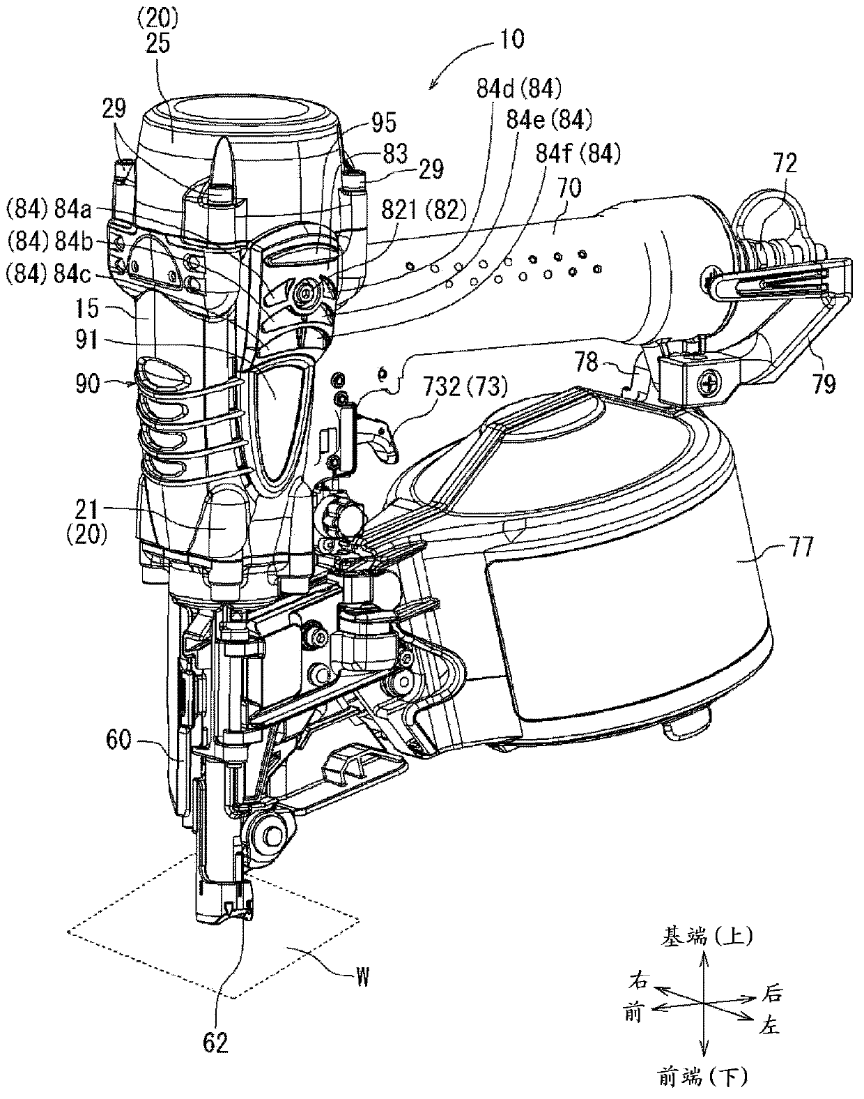
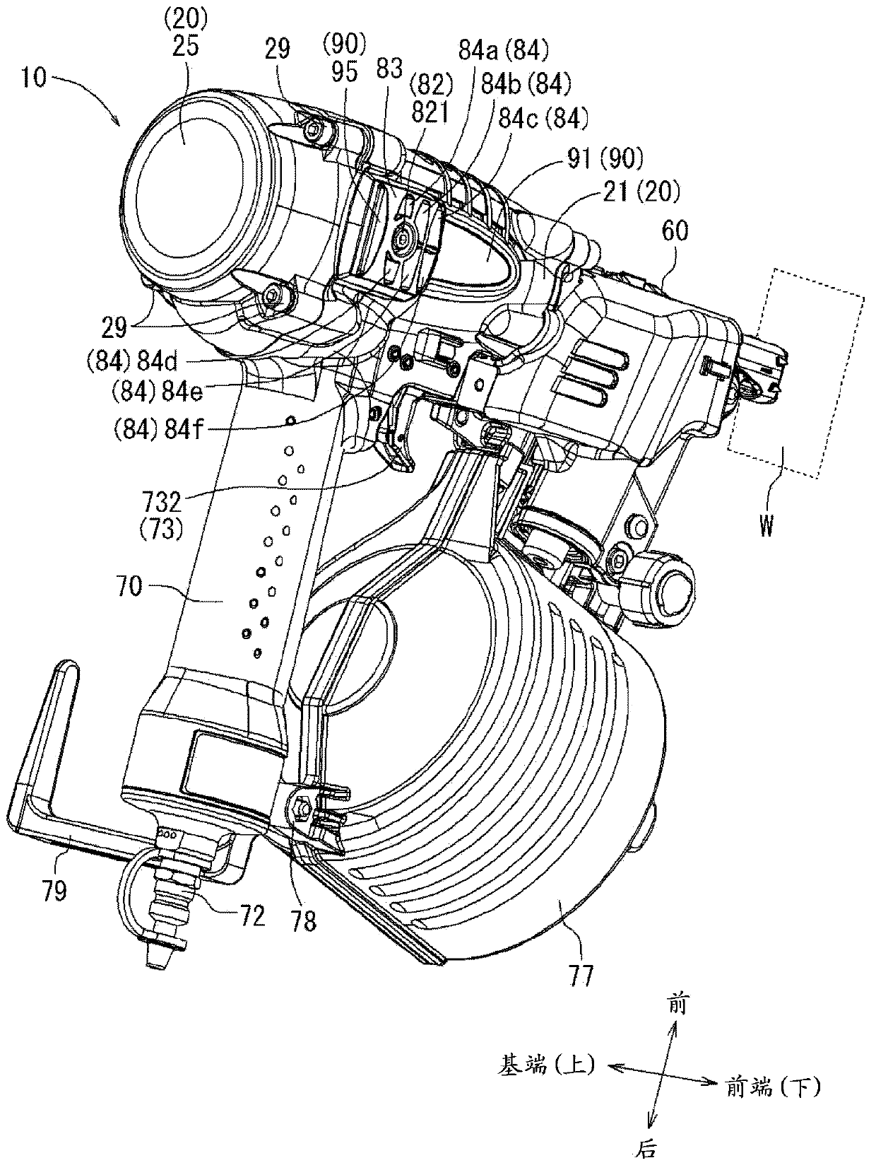
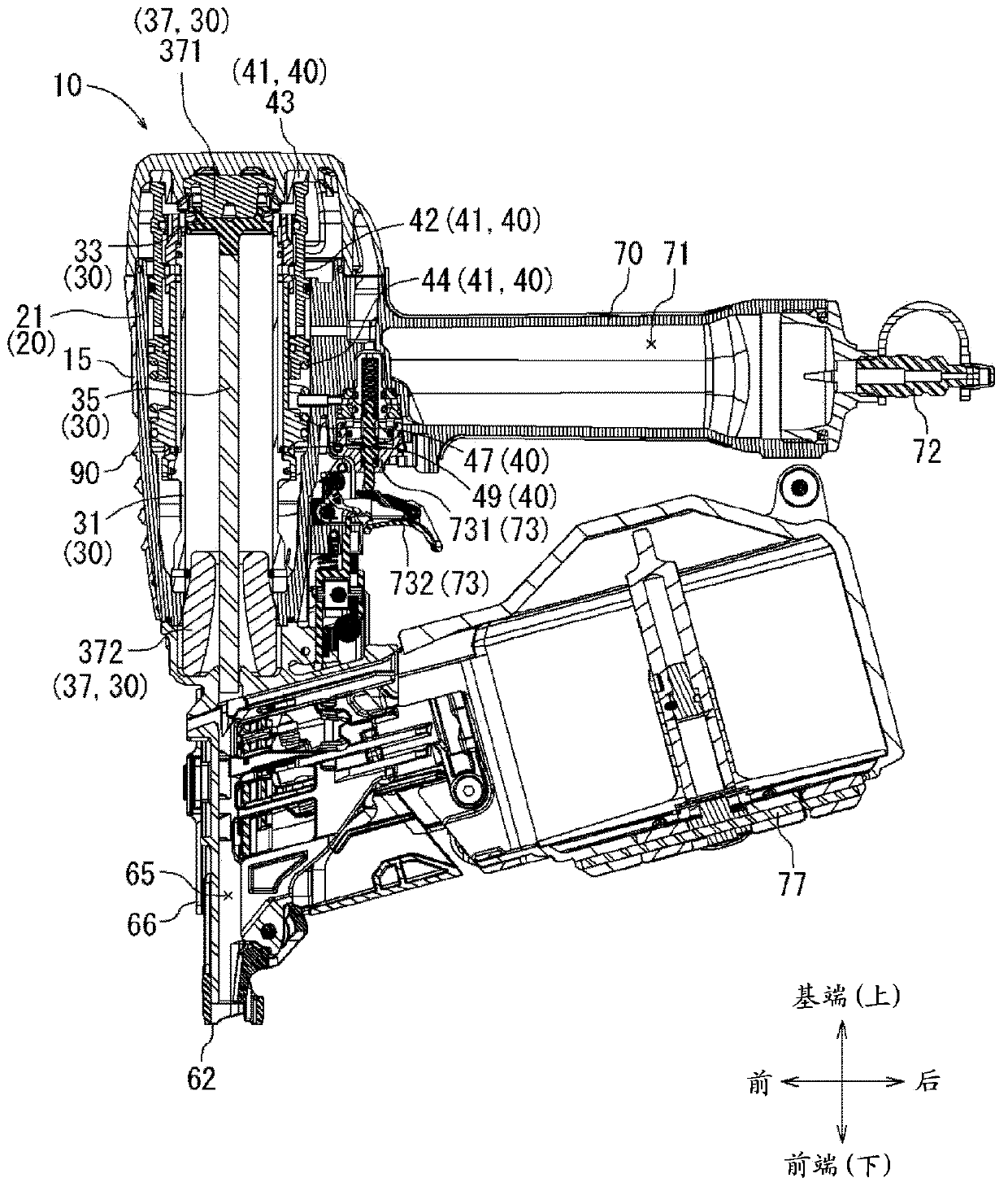
[0036] figure 1 as well as figure 2 In , an air driving tool 10 using compressed air as a driving source is shown. The air driving tool 10 is a driving tool configured as an air nail driving machine that drives a nail (not shown) as a driver. also, figure 1 This is an overall appearance view of the tool showing the overall appearance of the air driving tool 10 at an oblique angle. figure 2 so with figure 1 The overall appearance of the air driving tool 10 is shown at different oblique angles. image 3 This is an overall sectional view of the tool showing the internal structure of the air driving tool 10 in half section. in addition, Figure 4~Figure 7 It is a cross-sectional view showing the internal structure of the tool body 15 in the driving operation state of the air driving tool 10 . which is, Figure 4 is a cross-sec...


PUM


Abstract

The invention provides a pneumatic punching-in tool for driving in a punching-in member, capable for suppressing wind noise of exhausted compression air when the compression air as drive source is opened to atmosphere. When a punching-in operation of a punching-in actuator (35), compression air in an upper piston chamber (52) flows to a lower piston chamber, so that a piston (33) including the punching-in actuator (35) is reset to an initial position before punching-in operation. Exhaust channel at a side exhausting structure communicates with an exhaust channel for a trigger valve exhausting structure (74) which allows the force application air of a trigger valve (73) for opening and closing of an advancing head valve (41) to be exhausted to the outside of a tool body (15) through a communication channel (424), so that air not needed can be exhausted to the outside of a tool body (15) from the trigger valve exhausting structure (74). In addition, the trigger valve exhausting structure (74) is provided with a pressure releasing chamber (75) capable of expanding before air flowing in the trigger valve exhausting structure (74) is exhausted outside the tool body (15).

Description

technical field [0001] The present invention relates to an air type driving tool for driving a driving part by using compressed air as a driving source. Background technique [0002] As an air-type driving tool for driving a driver using compressed air as a driving source, for example, an air-type driver for driving a driver such as a nail is known. Such an air driving tool is configured to reciprocate a built-in piston by filling it with compressed air as a driving source or by opening it to the atmosphere. The piston is provided with a driving driver for driving a driver such as a nail toward a driving target, and the driving device can be driven toward the driving target by reciprocating movement of the driving driver. That is, such an air-type driving tool includes a tool body with a built-in piston, a driving part that drives a driving part by the action of the piston, and a handle part that is provided with an operation lever and can be held by hand. In the air-type ...

Claims


Application Information

Patent Timeline
Patent Type & Authority Applications(China)
IPC IPC(8): B25C1/04
Inventor 小宫行功纸元顺平
Owner MAKITA CORP
Why Eureka
Try Eureka