
Pneumatic tire

a technology of pneumatic tires and pneumatic cylinders, which is applied in the field of pneumatic tires, can solve the problems of cavernous resonance, cavernous resonance to be generated, tire noise, etc., and achieve the effect of preventing any reduction in high-speed durability and sufficient qui

Active Publication Date: 2021-09-14
THE YOKOHAMA RUBBER CO LTD
View PDF22 Cites 0 Cited by
  • Summary
  • Abstract
  • Description
  • Claims
  • Application Information

AI Technical Summary

Benefits of technology

The design effectively reduces heat buildup and maintains high-speed durability while achieving excellent quietness and ride comfort by optimizing the sound absorbing member's width and placement.

Problems solved by technology

One cause of tire noise is cavernous resonance caused by vibration of the air in the cavity portion (tire cavity) formed within the tire when mounted on a rim.
When a vehicle is run, uneven road surfaces cause a tread portion to vibrate on contact with the road surface, causing the air inside the tire cavity portion to vibrate which causes cavernous resonance to be generated.
However, with this structure, the sound absorbing member is directly applied to the tire inner surface, so that high speeds, heat can easily build up in the tread portion.
This accumulated heat can cause degradation of high-speed durability.

Method used


Image

  • Pneumatic tire
  • Pneumatic tire
  • Pneumatic tire

Examples


examples

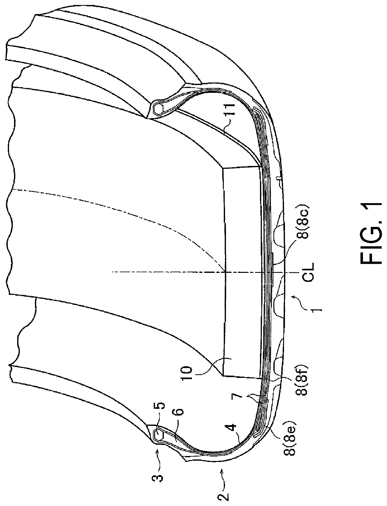
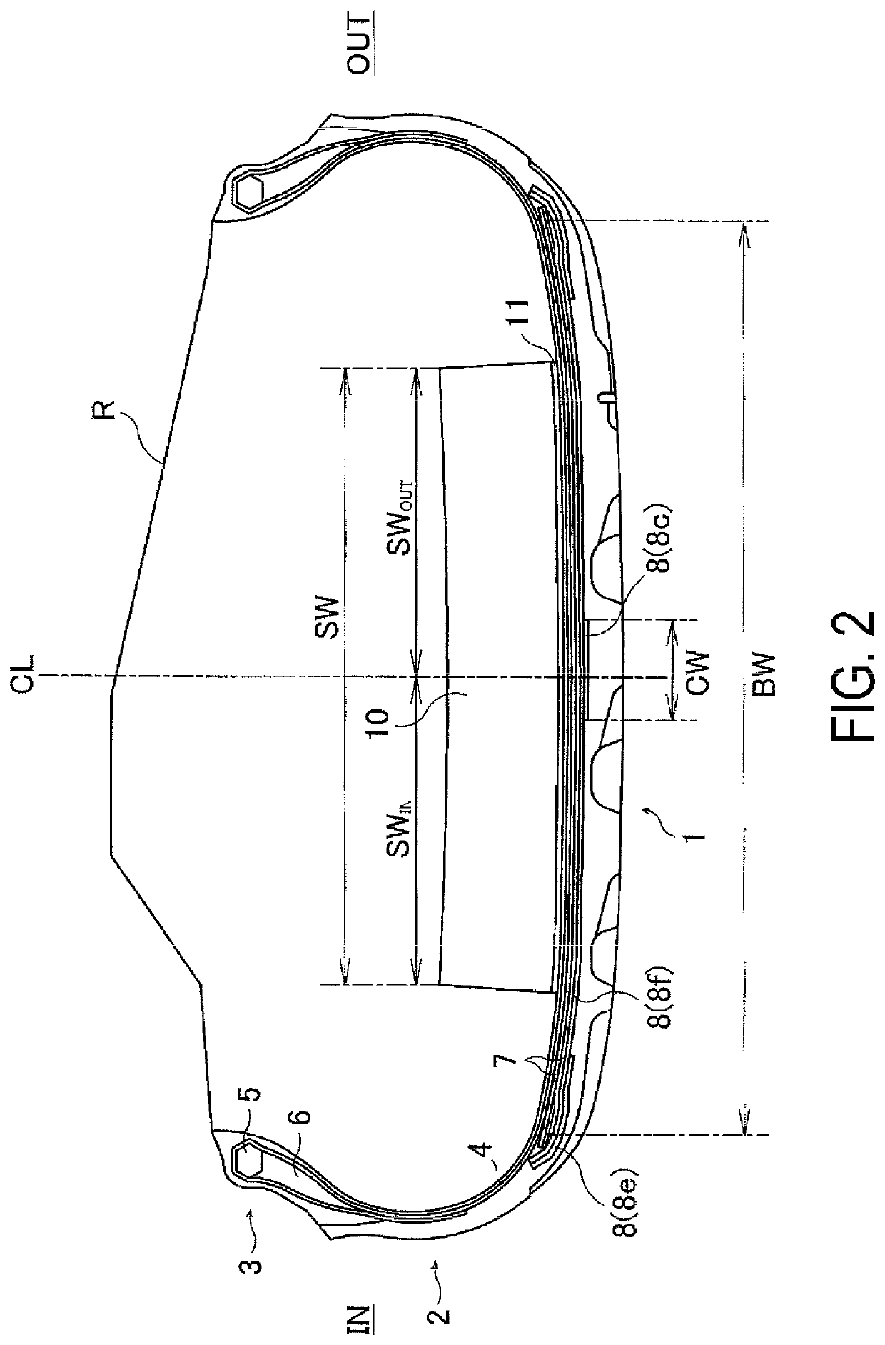
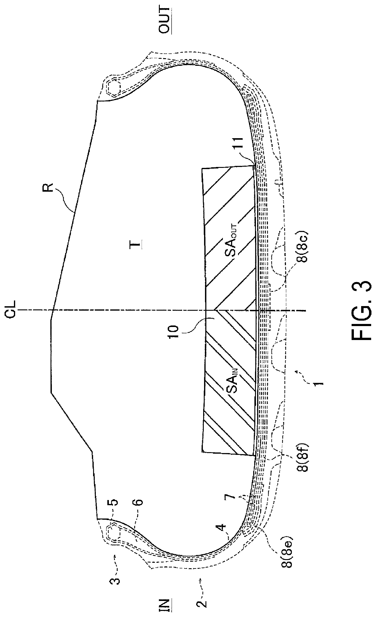
[0038]Sixteen different pneumatic tires with a tire size of 275 / 35ZR20 were manufactured having the basic structure illustrated in FIG. 1, to produce Conventional Example 1, Comparative Examples 1 to 4, and Examples 1 to 11. The following ratios of the widths and cross-sectional areas of each member (belt layer, center cover layer, and band-shaped sound absorbing member) were set as shown in Table 1: ratio SW / BW of the width SW of the band-shaped sound absorbing member and the width BW of the belt layer; ratio CW / SW of the width CW of the center cover layer and the width SW of the band-shaped sound absorbing member; ratio SWIN / CW of the width SWIN of the portion of the band-shaped sound absorbing member on the vehicle inner side and the width CW of the center cover layer 8c; ratio SWOUT / CW of the width SWOUT of the portion of the band-shaped sound absorbing member on the vehicle inner side and the width CW of the center cover layer 8c; ratio SWIN / SWOUT of the width SWOUT of the port...


PUM

PropertyMeasurementUnit
inclination angleaaaaaaaaaa
angleaaaaaaaaaa
thicknessaaaaaaaaaa

Abstract

A pneumatic tire includes a band-shaped sound absorbing member bonded along a tire circumferential direction to the tire inner surface in a tread portion; at least one full cover layer covering the entire width of belt layers on the outer circumferential side of the belt layers; and a center cover layer disposed on the outer circumferential side of the full cover layer, the center cover layer locally covering the tire lateral direction center region of the belt layers; a width SW of the band-shaped sound absorbing member and a width BW of the belt layers satisfying a relationship SW / BW=0.3 to 0.8, and a width CW of the center cover layer and the width SW of the band-shaped sound absorbing member satisfying the relationship CW / SW=0.05 to 0.35.

Description

TECHNICAL FIELD[0001]The present technology relates to a pneumatic tire equipped with a tire noise reduction device, and more particularly refers to a pneumatic tire that can achieve sufficient quietness via a band-shaped sound absorbing member attached to a tire inner surface and prevent a reduction in high-speed durability caused by the accumulation of heat in the band-shaped sound absorbing member at high speeds.BACKGROUND ART[0002]One cause of tire noise is cavernous resonance caused by vibration of the air in the cavity portion (tire cavity) formed within the tire when mounted on a rim. When a vehicle is run, uneven road surfaces cause a tread portion to vibrate on contact with the road surface, causing the air inside the tire cavity portion to vibrate which causes cavernous resonance to be generated. A specific frequency band of the cavernous resonance is perceived to be noise, so reducing the sound pressure level (noise level) of this frequency band is important for reducing ...

Claims


Application Information

Patent Timeline
Patent Type & Authority Patents(United States)
IPC IPC(8): B60C9/00B60C19/00B60C9/22B60C5/00B60C9/20B60C9/28B60C3/06
CPCB60C19/002B60C3/06B60C5/00B60C9/00B60C9/0042B60C9/2009B60C9/22B60C9/28B60C19/001B60C2009/2223B60C2009/2238
Inventor SHINZAWA, TATSURO
Owner THE YOKOHAMA RUBBER CO LTD
Learn More