Eureka AIR delivers breakthrough ideas for toughest innovation challenges, trusted by R&D personnel around the world.

Pneumatic Tire

Active Publication Date: 2019-05-30
YOKOHAMA RUBBER CO LTD
View PDF0 Cites 1 Cited by
  • Summary
  • Abstract
  • Description
  • Claims
  • Application Information

AI Technical Summary

Benefits of technology

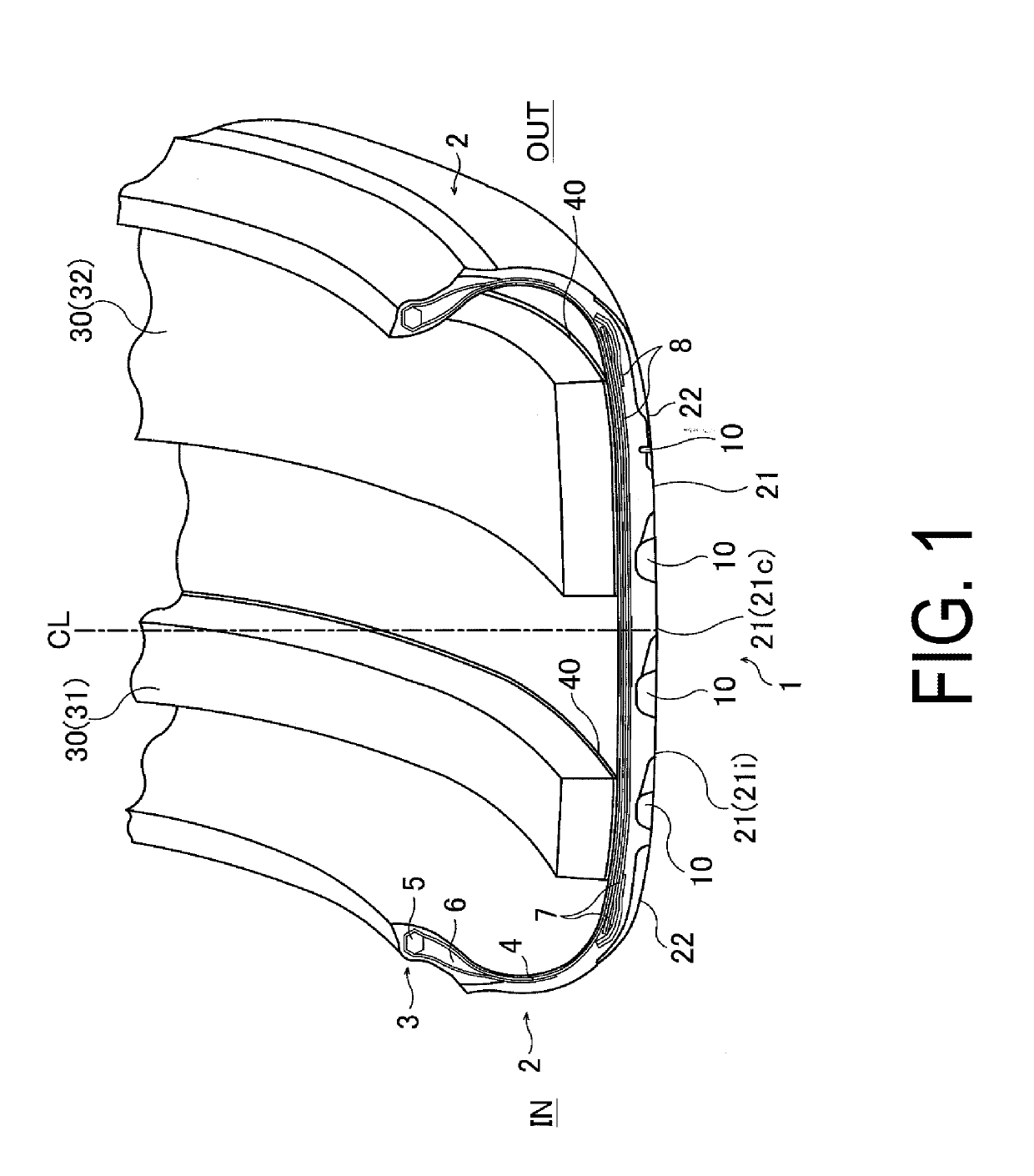
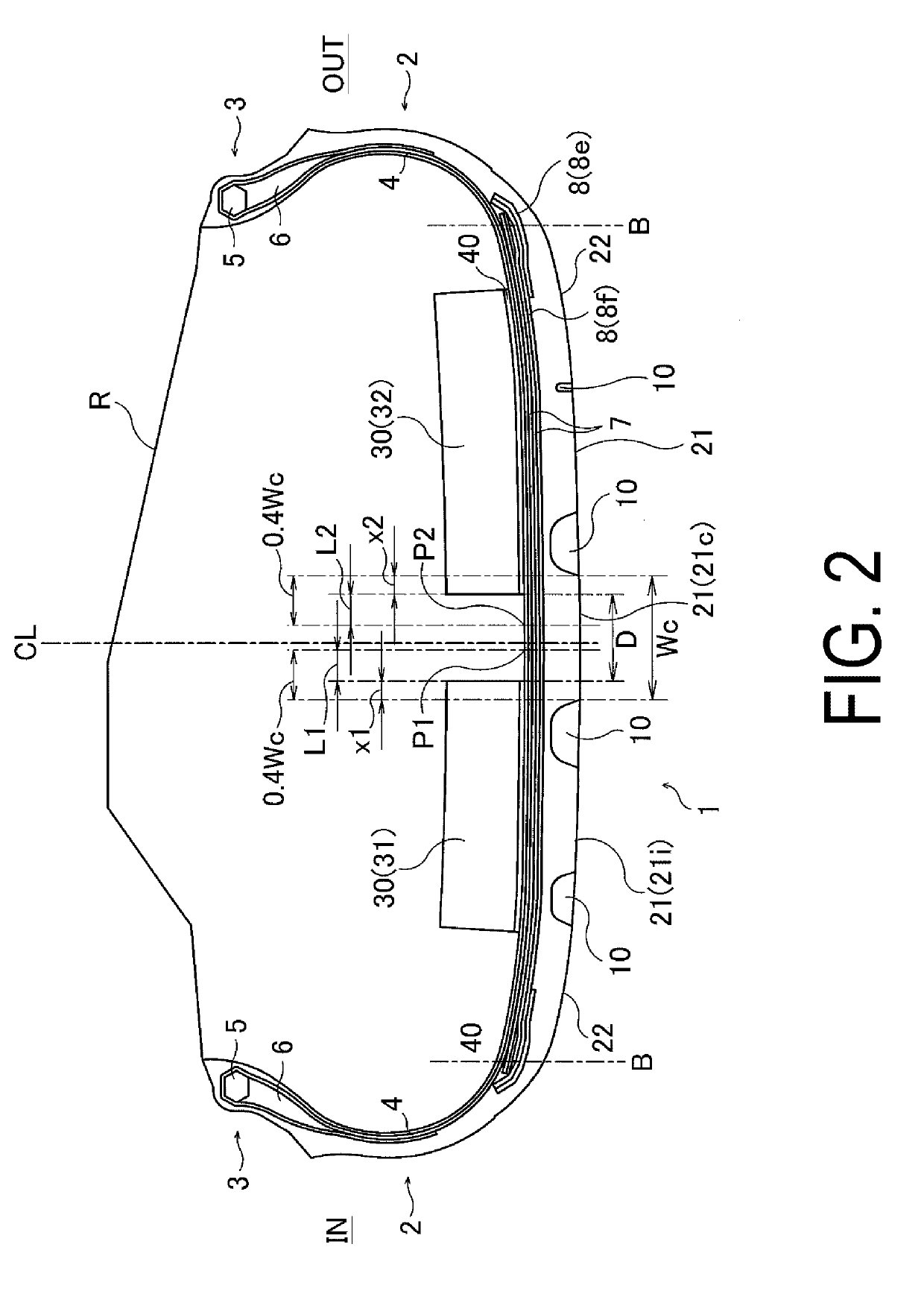
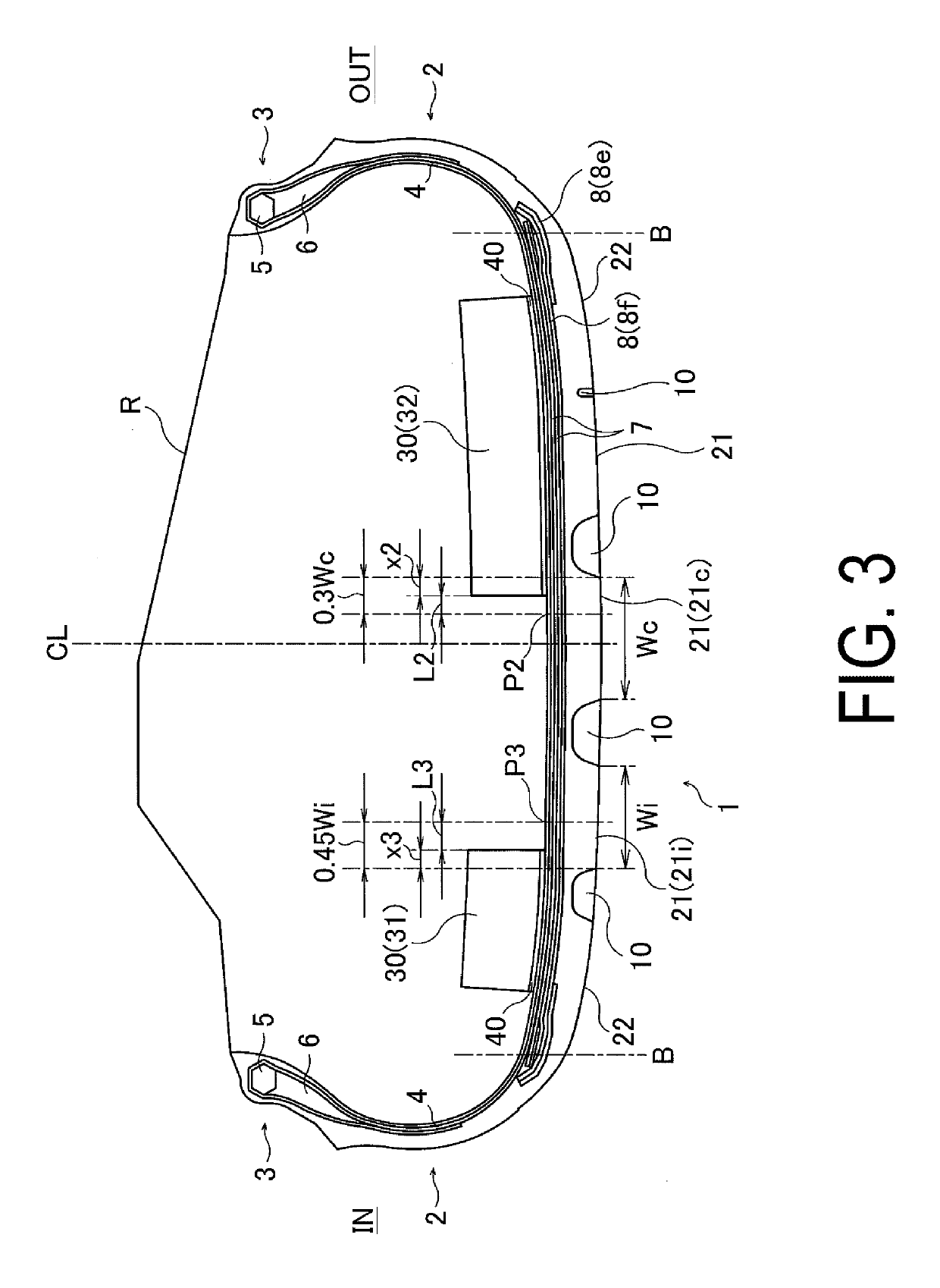
The present technology provides a pneumatic tire with a tire noise reduction device that prevents degradation in high-speed durability due to accumulated heat in a band-like sound absorbing member at high speeds while sufficient quietness is achieved. The technology achieves this by employing a pair of sound absorbing members that are separated from each other and positioned at the inner surface of the tire to avoid the inner surface side of the center land portion, in which heat is most liable to be generated. The volume ratio of the sound absorbing members to the tire cavity is set from 10% to 40% to ensure excellent sound absorbing performance. The first sound absorbing member or the second sound absorbing member is designated as the one side or the other side in the tire lateral direction to improve high-speed durability and noise performance in a well-balanced and compatible manner. The end portions of the sound absorbing members are disposed inward in the tire lateral direction to avoid influence from strain caused at the end portions of the belt layers and improve high-speed durability. The band-like sound absorbing members are tolerant to deformation of the tire during inflation and shearing strain at the contact surface due to rolling on ground for a long period of time.

Problems solved by technology

However, in this structure, the sound absorbing member is directly adhered on the tire inner surface, Thus, heat is liable to be accumulated in the tread portion at high speeds.
This causes a problem of degradation of the high-speed durability due to the accumulated heat.
In this case, the above-mentioned volume ratio is attempted to be achieved with a single sound absorbing member, accumulated heat in the sound absorbing member at high speeds is increased, and hence, the high-speed durability is adversely influenced.

Method used


Image

  • Pneumatic Tire
  • Pneumatic Tire
  • Pneumatic Tire

Examples


examples

[0034]Twenty-nine kinds of pneumatic tires in Conventional Examples 1 to 2, Comparative Examples 1 to 2, and Examples 1 to 26, each of which had a tire size of 275 / 35ZR20 and a basic configuration illustrated in FIG. 1, were manufactured with the following conditions set as shown in Tables 1 to 2: mounting direction with respect to the vehicle specified for the pneumatic tire, form of the sound absorbing member(s), volume ratio of the sound absorbing member(s), ratio of the volume V1 of the first sound absorbing member and the volume V2 of the second sound absorbing member (volume ratio of V2 / V1), the distances L1 to L3, separation direction D, amounts of overlap x1 to x3, amount of overlap X (sum of the amounts of overlap x1 and x2), position(s) of the end portion(s) of the sound absorbing member(s) on the outer side in the tire lateral direction, and the number of missing portions.

[0035]Note that, as for the column regarding the form of the sound absorbing member(s), when a single...


PUM


Abstract

In a pneumatic tire, first and second sound absorbing members are adhered to an inner surface of a tread, have a total volume ranging from 10% to 40% of a capacity of a tire cavity, and are separated from each other by 60% of the width of a center land. The first sound absorbing member is on one side in a lateral direction with respect to a position of 40% of a width of the center land from one end of the center land on one side in the lateral direction to the other side in the lateral direction. The second sound absorbing member is on the other side in the lateral direction with respect to a position of 40% of the width of the center land from the other end of the center land in the lateral direction to the one side in the lateral direction.

Description

TECHNICAL FIELD[0001]The present technology relates to a pneumatic tire including a tire noise reduction device and particularly relates to a pneumatic tire that can prevent degradation in high-speed durability due to accumulated heat in a sound absorbing member at high speeds while sufficient quietness is achieved by the sound absorbing member mounted on a tire inner surface.BACKGROUND ART[0002]One of the factors that generate tire noise is cavernous resonance caused by the vibration of the air filled in a cavity portion (tire cavity) formed in a tire when the tire is mounted on a rim. This cavernous resonance occurs when a tread portion of a tire that contacts a road surface vibrates due to unevenness or the like of the road surface when a vehicle is driven, and this vibration vibrates the air in the tire cavity. Because, among the cavernous resonance, sound in a particular frequency band is perceived as noise, it is important to reduce the level of sound pressure in the frequency...

Claims


Application Information

Patent Timeline
IPC IPC(8): B60C19/00B60C11/03
CPCB60C19/002B60C11/03B60C2011/0341B60C19/00B60C5/00B60C11/0304
Inventor SHINZAWA, TATSURO
Owner YOKOHAMA RUBBER CO LTD
Why Eureka
Eureka Blog
Learn More