Electric power steering system

a technology of electric power steering and steering shaft, which is applied in the direction of electric steering, power driven steering, vehicle components, etc., can solve the problems of affecting the steering feel, so as to achieve good steering feel, high reliability, and sufficient quiet

Inactive Publication Date: 2011-03-03
JTEKT CORP
View PDF8 Cites 4 Cited by
  • Summary
  • Abstract
  • Description
  • Claims
  • Application Information

AI Technical Summary

Benefits of technology

[0019]It is an object of the invention to provide an electric power steering system that makes it possible to secure a ball screw nut to a motor shaft without causing deformation, thereby achieving high reliability, sufficient quietness and good steering feel, and improving the working efficiency during production.

Problems solved by technology

However, employment of the above-described structure causes an increase in the diameter of a portion of the hollow shaft, at which the ball screw nut and the hollow shaft overlap each other.
Further, clamping the ball screw nut using the locknut may cause deformation of the ball screw nut, resulting in distortion of a thread groove that forms a ball-rolling path.
The distortion hinders smooth rolling of each ball in the ball-rolling path, which may cause abnormal sound, vibration, and deterioration of steering feel.
Fastening the flanges to each other with a plurality of bolts is cumbersome.
Therefore, it is difficult to increase the productivity.
However, it is difficult to form a threaded portion in the entirety of the outer periphery of a ball screw nut that has high strength and rigidity.
In addition, providing the ball screw nut in a hollow shaft causes upsizing of a portion of the hollow shaft at which the ball screw nut is located.
However, even if the structure in which the ball screw nut is screwed to the axial end portion of the hollow shaft is employed, there is still a problem that should be solved.
This structure makes it difficult to screw the ball screw nut to the motor shaft when the ball screw nut is screwed to the axial end portion of the motor shaft as described above.
However, in the structure in which the ball screw nut is screwed to the axial end portion of the motor shaft, it is not possible to form the above-described engaged portion in the axial end face to which the ball screw nut is screwed.
Therefore, it is difficult of restrict the free rotation of the motor shaft.
Accordingly, it is difficult to prevent the simultaneous rotation of the motor shaft and the ball screw nut in the same direction that is caused when the ball screw nut is screwed to the motor shaft, that is, it is difficult to prevent the motor shaft from rotating together with the ball screw nut.

Method used


Image

  • Electric power steering system
  • Electric power steering system
  • Electric power steering system

Examples


Embodiment Construction

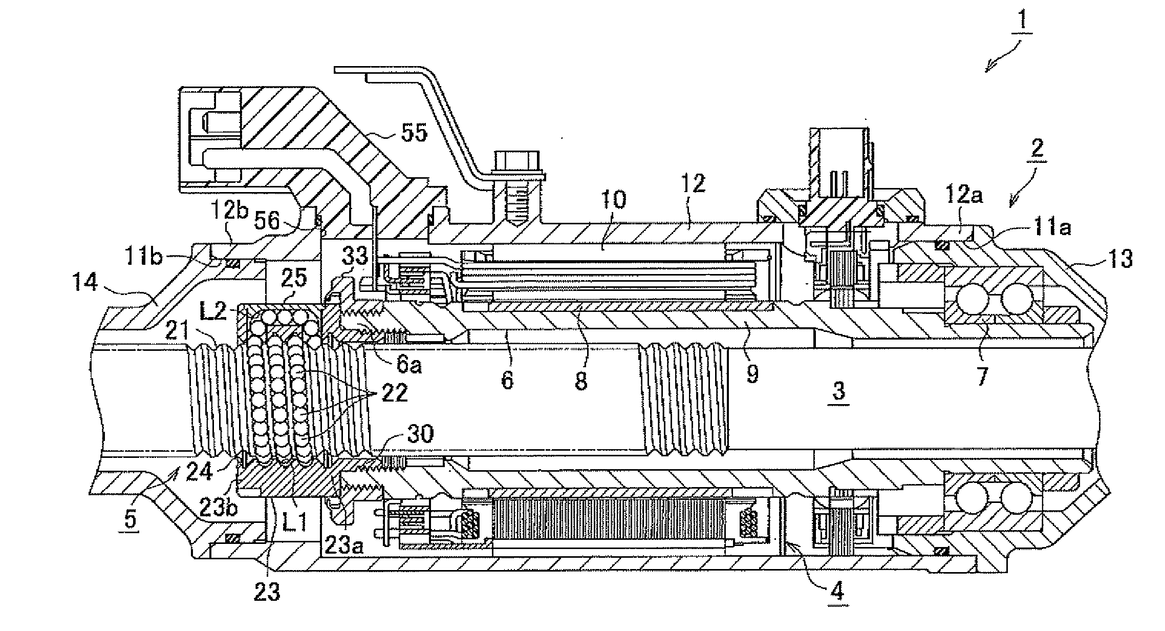
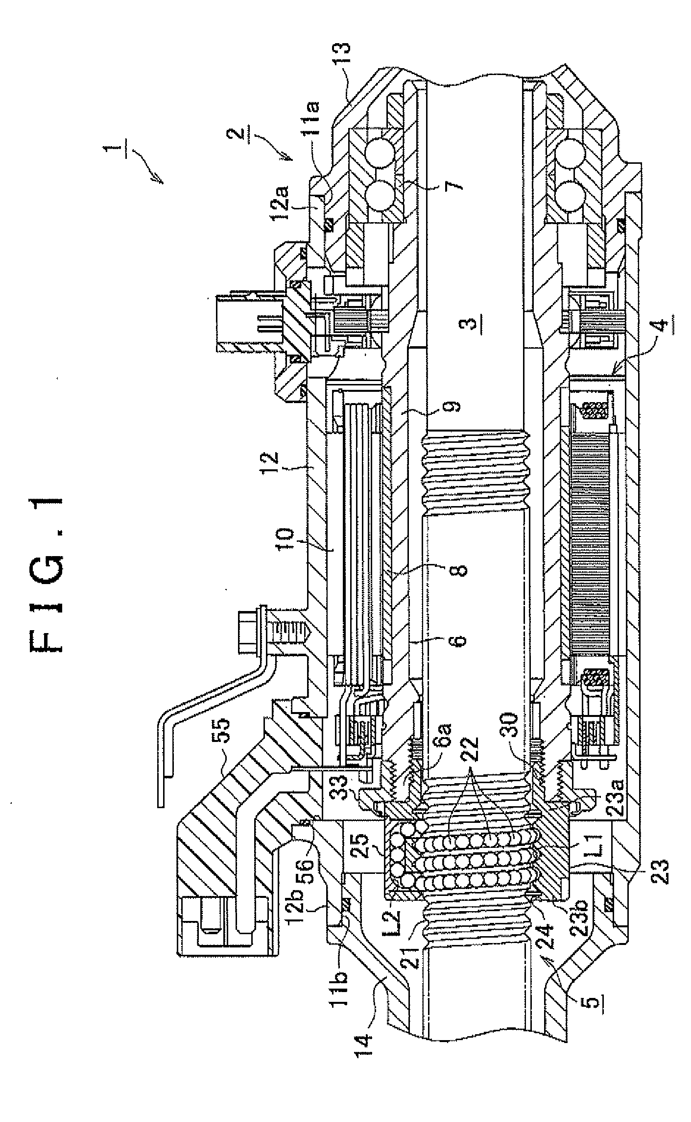
[0039]Hereafter, an embodiment of the invention will be described with reference to the accompanying drawings. As shown in FIG. 1, in an electric power steering system (EPS) 1 according to the embodiment, a rack shaft 3 that passes through a substantially cylindrical housing 2 is supported by a rack guide (not shown) and a plain bearing (not shown). Thus, the rack shaft 3 is supported and housed in the housing 2 so as to be movable along its axial direction. The rack shaft 3 is connected to a steering shaft via a known rack-and-pinion mechanism so that the rack shaft 3 reciprocates along the axial direction in response to a steering operation.

[0040]The EPS 1 includes a motor 4 that serves as a drive source, and a ball screw device 5 that converts the rotation of the motor 4 into axial movement of the rack shaft 3. The EPS 1 according to the embodiment is formed as a rack-assist-type EPS in which the rack shaft 3, the motor 4 and the ball screw device 5, which are fitted together, ar...


PUM


Abstract

In an electric power steering system, a ball screw nut (23) of a ball screw device that drives a rack shaft is screwed to an axial end portion (6a) of a motor shaft (6) when a threaded portion (31) of a hollow threaded shaft (30) formed at an axial end portion (23a) of the ball screw nut (23) is screwed to a threaded portion (32) formed in the inner periphery of a motor shaft (6). A flange member (33) that is larger in diameter than the ball screw nut (23) is fitted to the outer periphery of the axial end portion (6a) of the motor shaft (6). The flange member (33) is formed in such a manner that when the rotation of the flange member (33) is restricted, the rotation of the ball screw nut (23) and the motor shaft (6) in the same direction is restricted when the ball screw nut (23) is screwed to the motor shaft (6).

Description

INCORPORATION BY REFERENCE[0001]The disclosure of Japanese Patent Application No. 2009-199787 filed on Aug. 31, 2009 including the specification, drawings and abstract is incorporated herein by reference in its entirety.BACKGROUND OF THE INVENTION[0002]1. Field of the Invention[0003]The invention relates to an electric power steering system that includes a ball screw device.[0004]2. Description of the Related Art[0005]There is an existing rack-assist-type electric power steering system (EPS) that includes a hollow shaft, through which a rack shaft passes, and that converts the rotation of the hollow shaft rotated by a motor into axial movement of the rack shaft using a ball screw device to supply assist force to a steering system.[0006]In the EPS described above, the ball screw device is formed by arranging a plurality of balls between a ball screw nut secured to the hollow shaft and a threaded portion formed in the rack shaft. When a threaded portion formed in the inner periphery o...

Claims


Application Information

Patent Timeline
Patent Type & Authority Applications(United States)
IPC IPC(8): B62D5/04
CPCB62D5/0448B62D5/0427
Inventor ASAKURA, TOSHIHIROHARA, TAKASHI
Owner JTEKT CORP
Why Eureka
Try Eureka