
Height adjustable handles for wheelbarrows

a technology for adjustable height handles and wheelbarrows, which is applied in the direction of hand cart accessories, hand carts with one axis, vehicles, etc., can solve the problems of disadvantaged tall users, back injuries, and proximity of handles to the ground

Active Publication Date: 2021-09-14
GREEN IVAN L
View PDF12 Cites 3 Cited by
  • Summary
  • Abstract
  • Description
  • Claims
  • Application Information

AI Technical Summary

Benefits of technology

Enables users to adjust handles to a comfortable height, reducing the risk of back injuries and allowing taller individuals to use the wheelbarrow without strain, while maintaining stability and strength during loading and unloading.

Problems solved by technology

One particular problem with classic wheelbarrows is the proximity of the handles to the ground.
Such stooping may result in back injuries, if the handles are not lifted properly.
Another problem is that the handles are usually fixed in place, such that tall users are particularly disadvantaged in using such wheelbarrows.

Method used


Image

  • Height adjustable handles for wheelbarrows
  • Height adjustable handles for wheelbarrows
  • Height adjustable handles for wheelbarrows

Examples


Embodiment Construction

[0019]The following description of the preferred embodiment(s) is merely exemplary in nature and is in no way intended to limit the invention, its application, or uses.

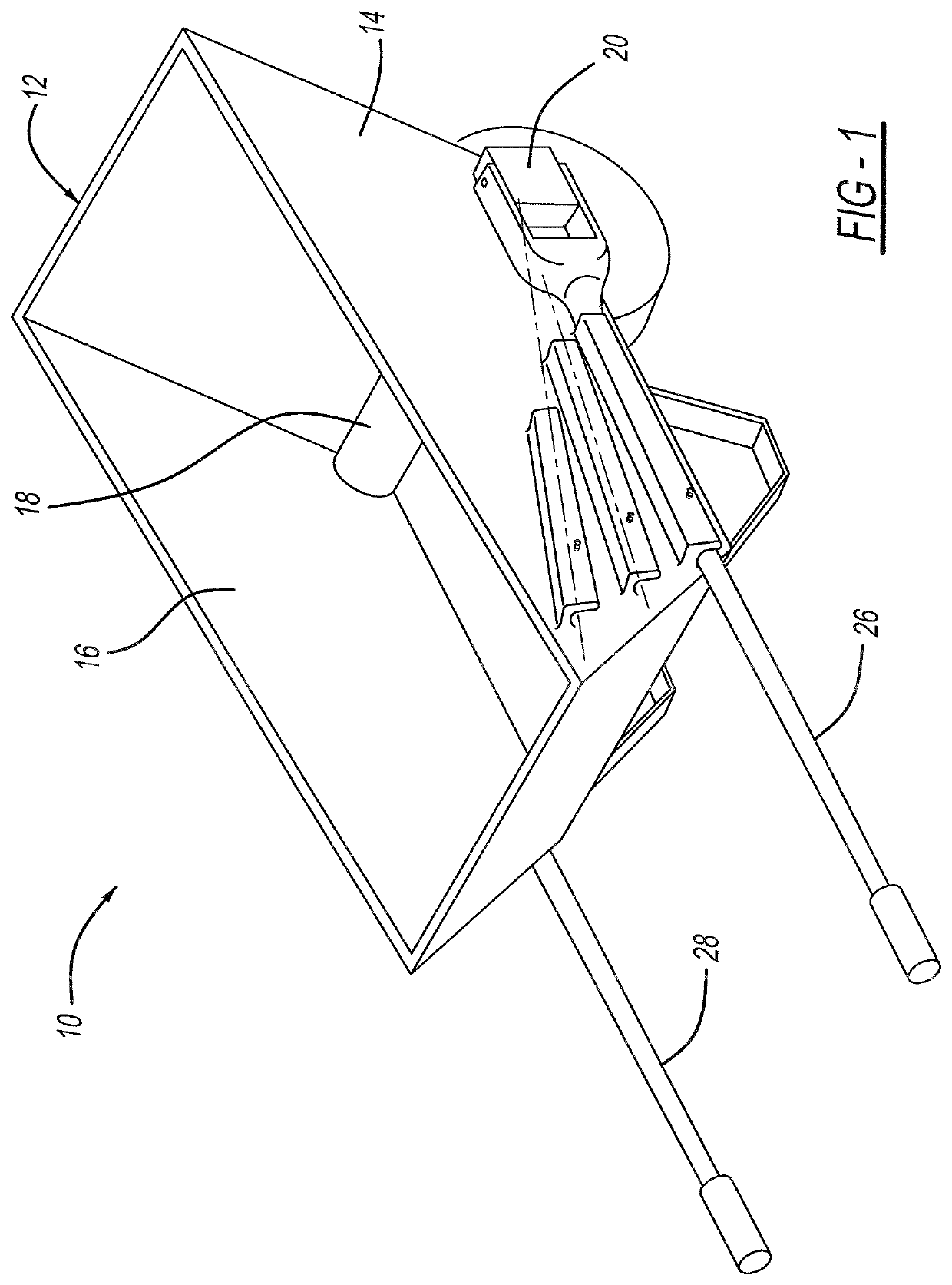
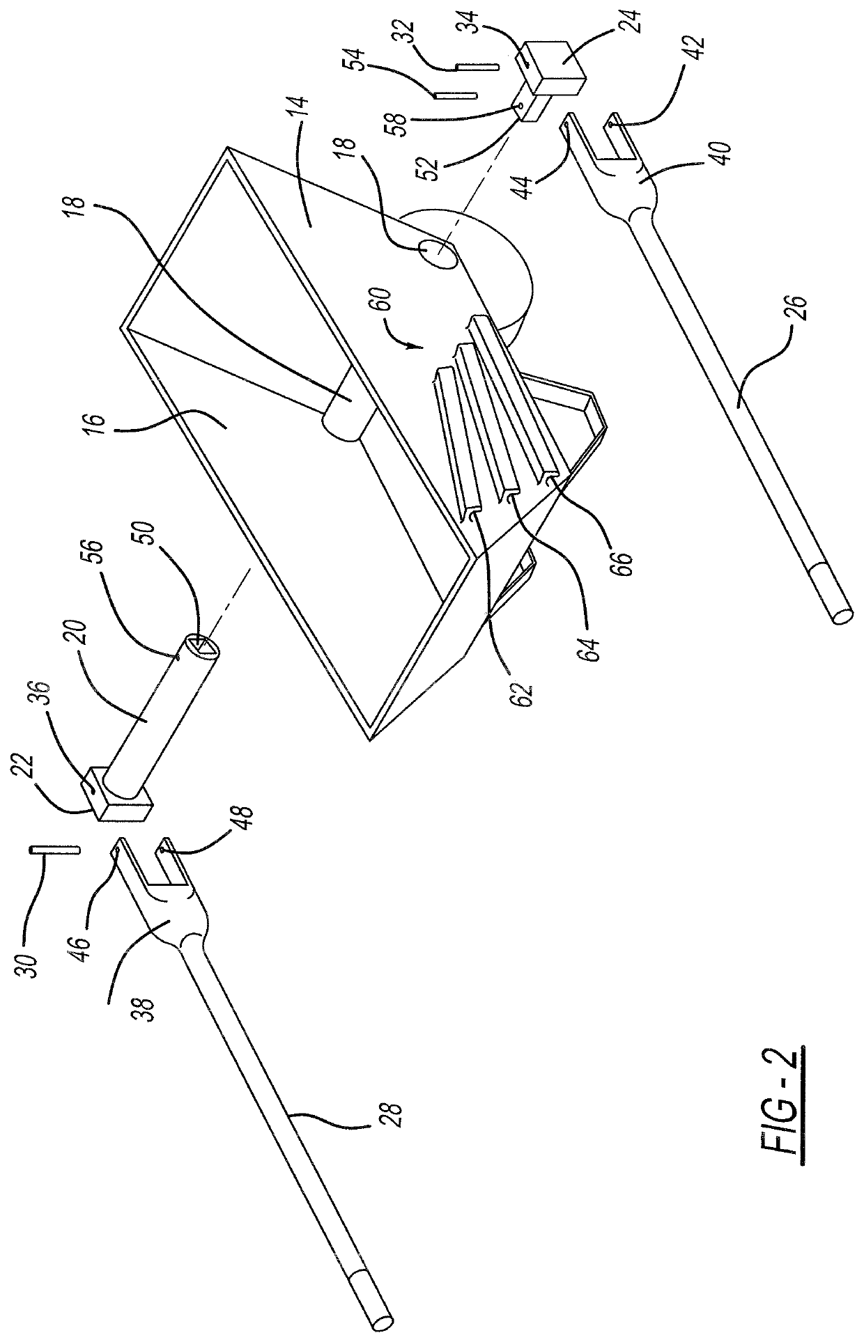
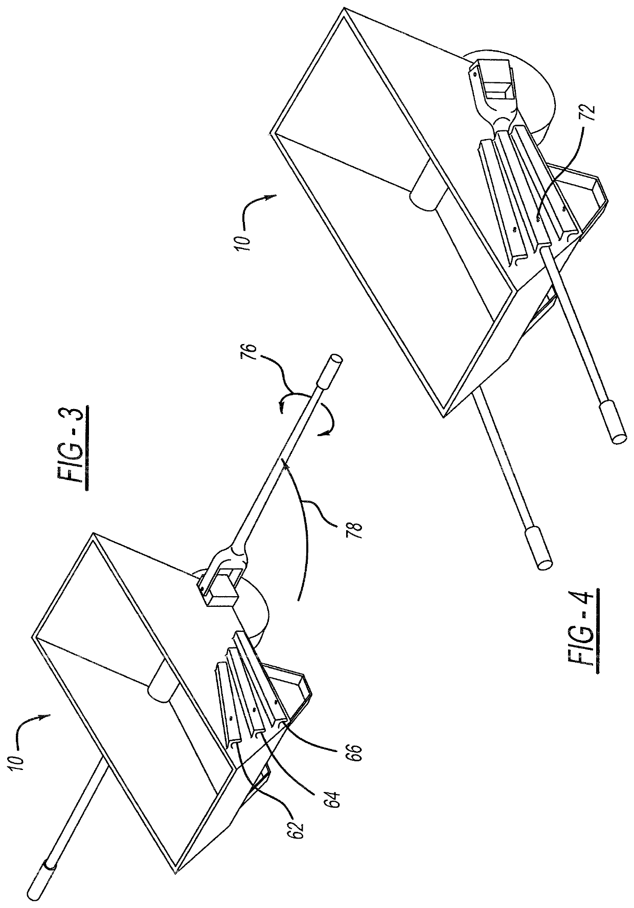
[0020]A wheelbarrow having an adjustable handle is generally shown at 10. The wheelbarrow 10 has a bucket portion 12 having a pair of sides 14 and 16 and an axle accepting portion 18 therein. An axle member 20 is provided for insertion through the axle accepting portion 18. The axle member 20 has a pair of outer peripheral ends (22, 24) spaced on either side of the pair of sides 14, 16. A pair of handles (26, 28) are pivotally attached to each of the pair of outer peripheral ends 22, 24 by way of pivot pins 30 and 32 for allowing the handle 26, 28 to pivot away from the bucket portion 12 of the wheelbarrow 10. Pivot Pins 30 and 32 engage orifices (42, 44, 46, 48) in U-shaped yokes 38 and 40 and corresponding holes 34 and 36 in the end portions 22 and 24.

[0021]The axle 18 is a two piece assembly which includes and end ...


PUM


Abstract

A wheelbarrow having an adjustable handle. The wheelbarrow has a bucket portion having a pair of sides and an axle accepting portion therein. An axle member is provided for insertion through the axle engagement member. The axle member has a pair of outer peripheral ends spaced on either side of the pair of sides. A pair of handles are pivotally attached to each of the pair of outer peripheral ends for allowing the handle to pivot away from the bucket portion of the wheelbarrow. Each side of the wheelbarrow has surfaces defining a plurality of handle engaging areas such that the handle may selectively be engaged in an area at a first position and selectively disengaged to move the handle to a second position. Each handle has a handle end portion which includes grip portions corresponding to the number of positions for the handles wherein each grip portion is configured at an angle for being substantially parallel to the ground when in a corresponding position in a selected corresponding slot in the wheelbarrow.

Description

CROSS-REFERENCE TO RELATED APPLICATIONS[0001]This application is a National Stage of PCT International Application No. PCT / US2018 / 031131, filed May 4, 2018, claims the benefit of U.S. Provisional Application No. 62 / 501,429, filed May 4, 2017, and U.S. Provisional Application No. 62 / 509,319, filed May 22, 2017. The disclosures of the above applications are incorporated herein by reference.TECHNICAL FIELD[0002]The present invention relates to garden carts and related apparatuses commonly referred to as wheelbarrows. More particularly the present invention relates to an adjustable height handle for a garden cart or wheelbarrow. The word “wheelbarrow” as used herein refers to garden carts or classic wheelbarrows.BACKGROUND OF THE INVENTION[0003]The wheelbarrow is a relatively ancient implement or vehicle for moving small to medium loads by human power. A “classic” wheelbarrow includes a V-shaped frame formed by angularly connected side members or shafts terminating in handles at their o...

Claims


Application Information

Patent Timeline
Patent Type & Authority Patents(United States)
IPC IPC(8): B62B1/20B62B5/06
CPCB62B1/20B62B5/062B62B5/064
Inventor GREEN, IVAN L.
Owner GREEN IVAN L
Learn More