Hand drying apparatus

a technology of hand drying and hand dryer, which is applied in the direction of lighting and heating apparatus, drying using combination processes, domestic applications, etc., can solve problems such as noise, and achieve the effects of preventing noise, excellent usability, and high drying performan

Active Publication Date: 2009-11-10
MITSUBISHI ELECTRIC CORP
View PDF57 Cites 47 Cited by
  • Summary
  • Abstract
  • Description
  • Claims
  • Application Information

AI Technical Summary

Benefits of technology

[0010]According to the hand drying apparatus of the present invention, the front side air nozzle and the back side air nozzle are formed by a plurality of slit-shaped ejecting holes arranged in a line, respectively, and both or any one of lengths of the slit-shaped ejecting holes and arranging intervals of the slit-shaped ejecting holes is different between the front side and the back side. Accordingly, it is possible to obtain a hand drying apparatus that can prevent noise without employing a complicated construction and realize high drying performance and excellent usability.
[0011]According to another aspect of the present invention, the front side air nozzle and the back side air nozzle are formed by a plurality of slit-shaped ejecting holes arranged in a line, respectively, and the slit-shaped ejecting holes on the front side are formed to be longer than the slit-shaped ejecting holes on the back side so that regions with different lengths where high-pressure airflows facing each other collide are formed on both sides of a region where the high-pressure airflows do not collide. Accordingly, without employing a complicated construction, noise can be prevented, drying performance and usability are improved, and a palm and a back of a hand can be dried in a balanced manner.
[0012]According to still another aspect of the invention, the front side air nozzle and the back side air nozzle are formed by a plurality of slit-shaped ejecting holes arranged in a line, respectively, and the arranging interval of the slit-shaped ejecting holes on the front side are formed to be shorter than the arranging interval of the slit-shaped ejecting holes on the back side so that regions with different lengths where high-pressure airflows facing each other collide are formed on both sides of a region where the high-pressure airflows do not collide. Therefore, without employing a complicated construction, noise can be prevented, drying performance and usability are improved, and a palm and a back of a hand can be dried in a balanced manner.

Problems solved by technology

Therefore, collisions between opposite jet flows cause turbulence and produce noise.

Method used


Image

  • Hand drying apparatus
  • Hand drying apparatus
  • Hand drying apparatus

Examples


Embodiment Construction

[0044]Exemplary embodiments of a hand drying apparatus according to the present invention are explained in detail below based on the drawings. Note that the present invention is not limited by these embodiments.

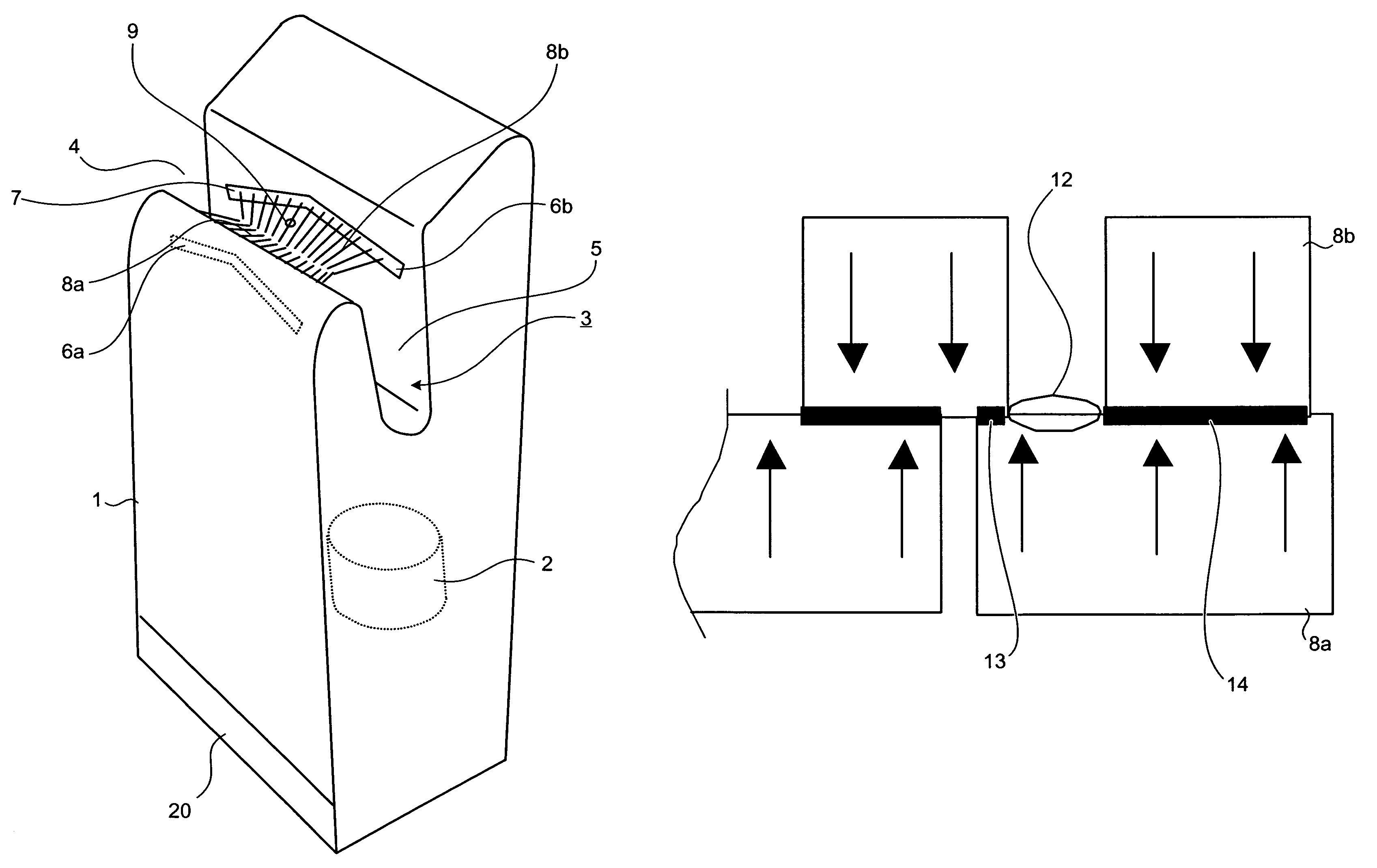
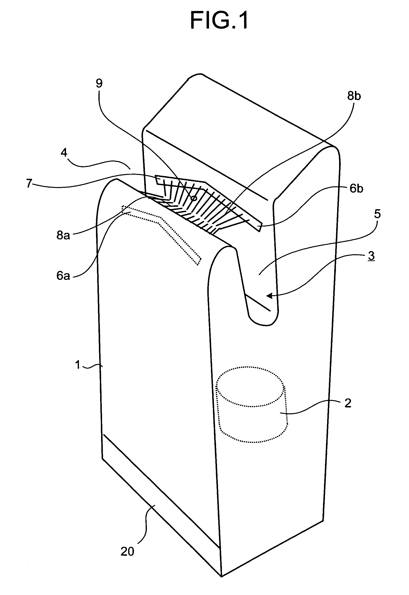
[0045]An embodiment of the present invention is explained with reference to FIG. 1 to FIG. 10. FIG. 1 shows an external appearance of a hand drying apparatus of the present embodiment. As shown in FIG. 1, this hand drying apparatus has a main body box case 1 that forms an outer sheath, having a hand inserting portion 3 on an upper portion. On an upper side of the main body box case 1, the hand inserting portion 3 is formed, which is a concave space formed by a hand inserting port 4 and a drying space 5 continued to the hand inserting port 4. The hand inserting portion 3 has a sink shape that is open at both sides and deep and inclined so that hands can be inserted and pulled out in a diagonally vertical direction, while both hands are aligned within a plane.

[0046]Inside the m...


PUM


Abstract

A hand drying apparatus includes a main body box case 1 that has a hand inserting portion 3 formed in a concave shape at an upper portion; a high-pressure airflow generator 2 that generates high-pressure airflows and is included in the main body box case; and a front side air nozzle 6a and a back side air nozzle 6b that eject the high-pressure airflows generated by the high-pressure airflow generator 2 into the hand inserting portion 3 and face each other. The front side air nozzle 6a and the back side air nozzle 6b are formed by a plurality of slit-shaped ejecting holes 7 arranged in a line, respectively, and both or any one of lengths and arranging intervals of the slit-shaped ejecting holes 7 is different between a front side and a back side. A hand drying apparatus that can prevent noise and realize high drying performance and excellent usability without employing a complicated construction is obtained.

Description

TECHNICAL FIELD[0001]The present invention relates to a hand drying apparatus that sanitarily dries wet hands after being washed by ejecting high-speed airflows.BACKGROUND ART[0002]Hand drying apparatuses that perform sanitary hand drying have been developed. These hand drying apparatuses blow moisture off by ejection of high-speed airflows to dry wet hands after being washed without wiping the hands with a towel or handkerchief. These types of hand drying apparatuses use kinetic energy of the high-speed airflows to blow moisture adhering to hands off. Therefore, collisions between opposite jet flows cause turbulence and produce noise.[0003]In the technology disclosed in Patent Document 1, one nozzle is provided with slit-shaped ejecting holes and an opposite nozzle is provided with circular ejecting holes roughly arranged in respective lines. Therefore, turbulence caused by collisions between the opposite jet flows is reduced, thereby suppressing noise.[0004]Patent Document 1: Japa...

Claims


Application Information

Patent Timeline
Patent Type & Authority Patents(United States)
IPC IPC(8): F26B7/00
CPCA47K10/48A61H9/005A61H33/08
Inventor KAMEISHI, KEIJIKOBAYASHI, TAKAKINAKAMURA, JUN
Owner MITSUBISHI ELECTRIC CORP
Why Eureka
Try Eureka