Hammer head with interference fit

a technology of hammer head and hammer head, which is applied in the direction of hand hammer, manufacturing tools, fastening means, etc., can solve the problems of stress concentrations where the components meet, and achieve the effects of reducing the area where the hammer head could come apart, limiting stress concentrations, and maximizing surface area overlap

Active Publication Date: 2021-10-19
SNAP ON INC
View PDF23 Cites 0 Cited by
  • Summary
  • Abstract
  • Description
  • Claims
  • Application Information

AI Technical Summary

Benefits of technology

[0004]The present invention broadly comprises a dead blow hammer head with end caps coupled to a central body through a flared interference fit. The ends of the body can be flared axially and radially outward and interference fit with recesses in both the front and rear end caps. The interference fit maximizes the surface area overlap between the ends of the body and the recesses, limiting the stress concentrations and reducing areas where the hammer head could come apart. A shot or other mass could also be implemented within the hammer head without obstructions such as screws or through pins. The interference fit can also become stronger during use, with the force and impact during use causing a tighter interference fit.

Problems solved by technology

Assembling multiple components, however, results in stress concentrations where the components meet.

Method used


Image

  • Hammer head with interference fit
  • Hammer head with interference fit
  • Hammer head with interference fit

Examples


Embodiment Construction

[0012]While this invention is susceptible of embodiments in many different forms, there is shown in the drawings, and will herein be described in detail, a preferred embodiment of the invention with the understanding that the present disclosure is to be considered as an exemplification of the principles of the invention and is not intended to limit the broad aspect of the invention to embodiments illustrated. As used herein, the term “present invention” is not intended to limit the scope of the claimed invention and is instead a term used to discuss exemplary embodiments of the invention for explanatory purposes only.

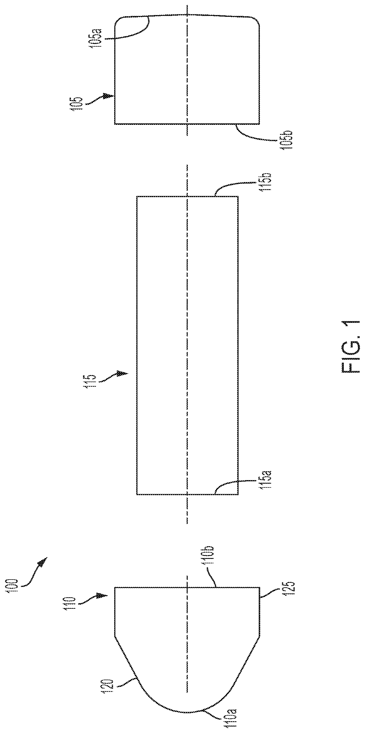
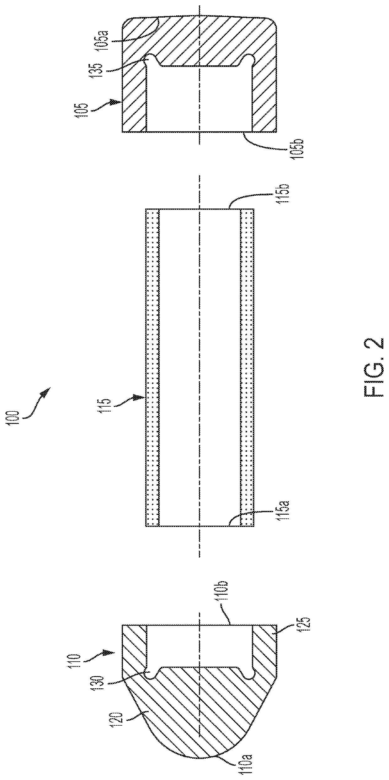
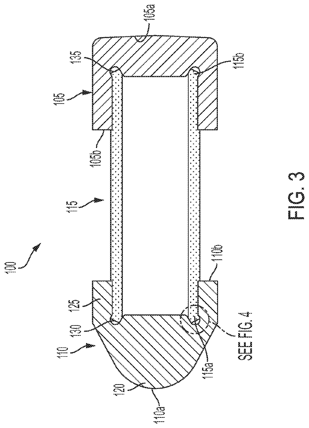
[0013]The present invention broadly comprises a dead blow hammer head that utilizes an interference fit to better couple end caps to a central body. The body can have ends that are flared axially and radially outward and insert into corresponding recesses in the end caps. The coupling between the ends and recesses can be an interference fit to maximize the surface area ...


PUM


Abstract

A dead blow hammer head with end caps coupled to a central body through an interference fit. The ends of the body can be flared axially and radially outward and interference fit with the recesses to maximize the surface area overlap between the ends of the body and the recesses. By maximizing the surface area overlap, stress concentrations and failure are reduced. The hammer head can also include a shot or other mass that is unobstructed by screws or pins due to the interference fit of the hammer head components. The interference fit can become stronger during use with each impact further solidifying the surface area overlap between the ends and central portion of the hammer head.

Description

TECHNICAL FIELD OF THE INVENTION[0001]The present invention relates generally to hammer heads. More particularly, the present invention relates to hammer heads with end caps coupled to a body with an interference fit.BACKGROUND OF THE INVENTION[0002]Hammer heads are well known tools for striking a work piece. Hammer heads are coupled to the end of a handle and swung towards the work piece. A hammer head can include a striking face that strikes the work piece and, upon impact, drives the work piece into a working surface. The force felt by the user upon impact is often referred to as a “rebound” that skilled artisans have worked to dampen.[0003]Dead blow hammer heads often include a mass inside the hammer head that dampens the rebound force of the hammer. For example, dead blow hammer heads can include a “shot” or another mass that is capable of flowing so as to absorb the impact of the hammer. Because of this internal mass, the hammer head must be assembled as opposed to cast as a s...

Claims


Application Information

Patent Timeline
Patent Type & Authority Patents(United States)
IPC IPC(8): B25D1/12B25D1/14B25D1/02F16B11/00
CPCB25D1/12B25D1/02B25D1/14F16B11/002B25D1/00F16B4/004
Inventor BENDORF, SCOTT A.
Owner SNAP ON INC
Why Eureka
Try Eureka