Lubricating device for components within casing structure of vehicular power transmitting system

a technology of lubricating device and transmission system, which is applied in the direction of transportation and packaging, drip or splash lubrication, vehicle sub-unit features, etc., can solve the problem of increasing the risk of torque loss of the transmission system, and achieve the effect of reducing the torque loss

Active Publication Date: 2021-10-19
TOYOTA JIDOSHA KK
View PDF23 Cites 10 Cited by
  • Summary
  • Abstract
  • Description
  • Claims
  • Application Information

AI Technical Summary

Benefits of technology

[0005]The present invention was made in view of the background art described above. It is therefore an object of the present invention to provide a lubricating device including a catcher reservoir and configured to lubricate components within a casing structure of a power transmitting system of a vehicle, which lubricating device permits reduction of a torque loss of the power transmitting system due to stirring of a lubricant oil at a high running speed of the vehicle.
[0011]In the lubricating device according to the first mode of the invention, the inclination angle of the first lubricant guide plate is determined to permit the lubricant oil guided by the first lubricant guide plate to be directed into the catcher reservoir, and to inhibit the lubricant oil from being supplied to at least one of the components which is disposed above the above-indicated gear. Accordingly, the lubricant oil guided by the first lubricant guide plate is effectively directed into the catcher reservoir. On the other hand, the inclination angle of the second lubricant guide plate is determined to permit the lubricant oil guided by the second lubricant guide plate to be supplied to the at least one of the components which is disposed above the above-indicated gear. Accordingly, a portion of the lubricant oil guided by the second lubricant guide plate is supplied to the component or components disposed above the above-indicated gear. Therefore, the amount of the lubricant oil directed into the catcher reservoir in the present lubricating device is made smaller than in a prior art lubricating device wherein both of first and second lubricant guide plates are formed so as to effectively direct the lubricant oil into the catcher reservoir, so that the amount of the lubricant oil overflowing from the catcher reservoir is reduced even at a high running speed of the vehicle. Accordingly, it is possible to prevent or reduce a power loss of the power transmitting system due to stirring of the overflow lubricant oil. At a low running speed of the vehicle, the lubricant oil guided by the second lubricant guide plate is supplied to the predetermined components of the power transmitting system. Namely, it is possible to prevent insufficient supply of the lubricant oil to the predetermined components even at the low running speed of the vehicle.
[0012]In the lubricating device according to the second mode of the invention wherein the first lubricant guide plate is formed within the first casing member while the second lubricant guide plate is formed within the second casing member, the first and second lubricant guide plates having the different inclination angles can be easily formed within the respective first and second casing members of the casing structure.
[0013]In the lubricating device according to the third mode of the invention, the first lubricant guide plate can be easily formed as an integral part of the first casing member formed by casting, and the second lubricant guide plate can also be formed as an integral part of the second casing member formed by casting.
[0014]In the lubricating device according to the fourth mode of the invention wherein the helix angle of the helical gear is determined such that the lubricant oil splashed up by the helical gear is scattered in the direction toward the first lubricant guide plate, the lubricant oil splashed up by the helical gear can be effectively directed into the catcher reservoir through the first lubricant guide plate. In addition, the amount of the lubricant oil to be directed into the catcher reservoir can be suitably adjusted by adjusting the helix angle of the helical gear.

Problems solved by technology

Where the amount of the lubricant oil stored in the catcher reservoir exceeds a storage capacity of the catcher reservoir, the lubricant oil overflowing from the catcher reservoir is again splashed up by the counter drive gear and the other gears, so that there is a risk of increase of a torque loss of the power transmitting system due to stirring of the lubricant oil by the gears.

Method used


Image

  • Lubricating device for components within casing structure of vehicular power transmitting system
  • Lubricating device for components within casing structure of vehicular power transmitting system
  • Lubricating device for components within casing structure of vehicular power transmitting system

Examples


embodiment

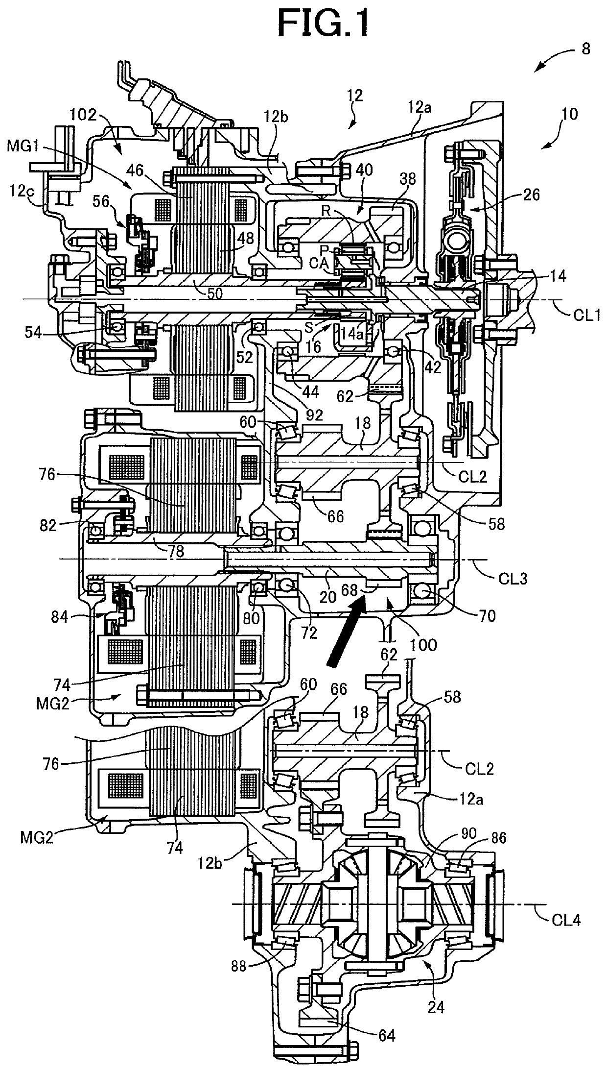
[0020]Reference is first made to FIG. 1, which is the cross sectional view of a power transmitting system 10 of a hybrid vehicle 8, which is provided with a lubricating device according to one embodiment of this invention. The power transmitting system 10 includes an engine (not shown), and a second electric motor MG2, and the hybrid vehicle 8 is of an FF type (front-engine front-drive type) which is driven with one or both of the engine and the second electric motor MG2.

[0021]The power transmitting system 10 includes: an input shaft 14, a power distributing mechanism 16 and a first electric motor MG1 which are disposed on a first axis CL1; a counter shaft 18 disposed on a second axis CL2; a speed reduction shaft 20 and the above-indicated second electric motor MG2 which are disposed on a third axis CL3; and a differential gear device 24 disposed on a fourth axis CL4. These components are accommodated within a casing structure 12.

[0022]The input shaft 14 is disposed rotatably about ...


PUM


Abstract

A lubricating device for lubricating components includes first and second lubricant guide plates which have respective inclination angles with respect to a horizontal line such that the angle of inclination of the first lubricant guide plate is smaller than that of the second lubricant guide plate. The inclination angle of the first lubricant guide plate is determined to permit the lubricant oil guided by the first lubricant guide plate to be directed into the catcher reservoir, and to inhibit the lubricant oil from being supplied to component or components disposed above the gear, and the inclination angle of the second lubricant guide plate is determined to permit the lubricant oil guided by the second lubricant guide plate to be supplied to the component or components disposed above the gear.

Description

[0001]This application claims priority from Japanese Patent Application No. 2017-244536 filed on Dec. 20, 2017, the disclosure of which is herein incorporated by reference in its entirety.FIELD OF THE INVENTION[0002]The present invention relates to a lubricating device for lubrication of components within a casing structure of a vehicular power transmitting system.BACKGROUND OF THE INVENTION[0003]There is known a lubricating device for lubricating various components within a casing structure of a vehicular power transmitting system. The lubricating device is configured such that a lubricant oil splashed up by rotation of a differential ring gear accommodated within the casing structure is supplied to the various components such as gears, while the lubricant oil is stored in a catcher reservoir. JP5790630B2 discloses an example of such a lubricating device. This publication describes that a differential ring gear, a counter drive gear, a counter driven gear and a catcher reservoir of...

Claims


Application Information

Patent Timeline
Patent Type & Authority Patents(United States)
IPC IPC(8): F16H57/04F01M9/06F16H57/02F16H57/037
CPCF16H57/0423F01M9/06F16H57/02F16H57/045F16H57/0409F16H57/0457F16H57/0476B60Y2306/03F16H57/037B60K6/405B60K6/445F16H57/0428F16H57/043F16H57/0441F16H57/0483F16H57/0486F16H57/0494F16H2057/02008Y02T10/62
Inventor HAGINO, YOSHITERUKATAYAMA, YUKIKAMIYA, KAZUAKI
Owner TOYOTA JIDOSHA KK
Why Eureka
Try Eureka