
Reflective diffusing lens and light emitting module comprising the same

a technology of reflector and light emitting module, which is applied in the direction of instruments, semiconductor devices, condensers, etc., can solve the problems of uniform light luminance of backlight units, difficult to achieve sufficient light diffusion, and deterioration of display quality of lcd, so as to improve luminance mura and improve light diffusion.

Active Publication Date: 2021-10-19
MOLEX INC
View PDF7 Cites 0 Cited by
  • Summary
  • Abstract
  • Description
  • Claims
  • Application Information

AI Technical Summary

Benefits of technology

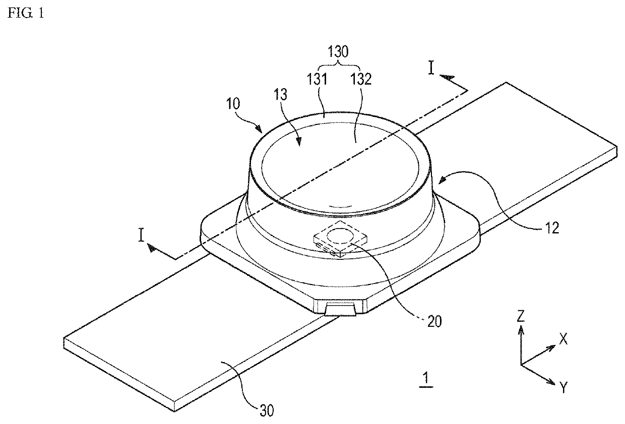
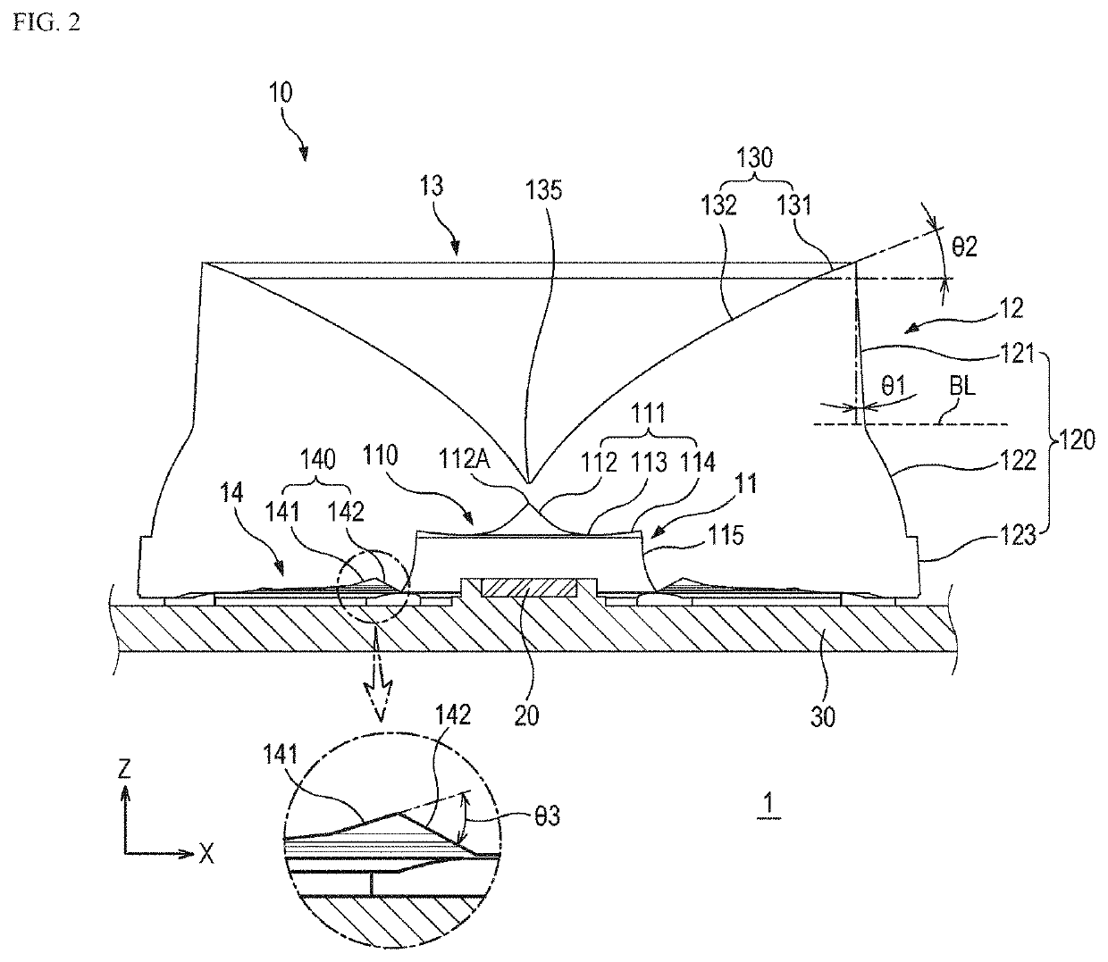
[0008]Objects of various embodiments of the present disclosure are to improve the diffusion of light by increasing an amount of reflection of light to be reflected inside a lens. Further, an object of the present disclosure is to provide a diffusing lens that minimizes occurrence of luminance mura and distributes light evenly, and a light emitting module comprising the same.
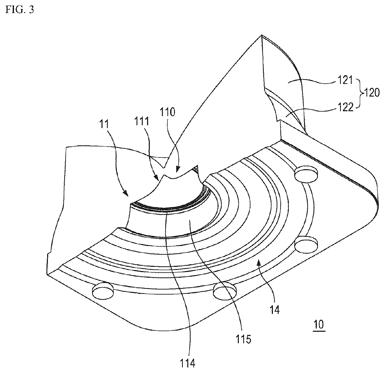
[0021]According to the embodiments of the present disclosure, it is possible to improve the diffusion of light by forming a re-reflection surface on a lower portion of a diffusing lens. Further, it is possible to improve luminance mura by forming a micro pattern on an upper surface of a light incident part of the diffusing lens.

Problems solved by technology

However, since a portion capable of reflecting light is not sufficiently provided in the corresponding diffusing lens, there is a problem in that it is difficult to implement a sufficient level of light diffusion.
However, there is still a need for a higher level of light diffusion, and there is a problem in that the light luminance of the backlight unit is ununiform due to the occurrence of luminance mura on the emission surface to deteriorate the display quality of the LCD.
If the number of LED light emitting elements is increased to prevent such mura, there is a problem in that cost and power consumption are increased.

Method used


Image

  • Reflective diffusing lens and light emitting module comprising the same
  • Reflective diffusing lens and light emitting module comprising the same
  • Reflective diffusing lens and light emitting module comprising the same

Examples


Embodiment Construction

[0045]Embodiments of the present disclosure are exemplified for the purpose of describing the technical spirit of the present disclosure. The scope according to the present disclosure is not limited to embodiments to be described below or to detailed descriptions of these embodiments.

[0046]All technical and scientific terms used in the present disclosure, unless defined otherwise, have meanings generally understood by those skilled in the art to which the present disclosure pertains. All terms used in the present disclosure are selected for the purpose of more clearly describing the present disclosure and are not selected to limit the scope according to the present disclosure.

[0047]As used in this disclosure, expressions such as “comprising”, “including”, “having,” etc. will be understood as open-ended terms that imply the possibility of including other embodiments, unless otherwise stated in the phrases or sentences in which the expressions are included.

[0048]The expression of sing...


PUM

PropertyMeasurementUnit
constant angleaaaaaaaaaa
angleaaaaaaaaaa

Abstract

Provided is a reflective diffusing lens which controls light emitted from a light emitting element according to an embodiment. The reflective diffusing lens is a reflective diffusing lens controlling the light emitted from the light emitting element and may comprise a light incident part which is formed concavely toward an upper side and has an incident surface to which the light emitted from the light emitting element is incident; a light emitting part which has an emission surface to which the light incident to the incident surface is emitted; a reflection part which is disposed at the upper side of the light incident part and formed concavely toward a lower side, and has a reflection surface on which a part of the light emitted from the light incident part is reflected; and a re-reflection part which is formed outside a radial direction of the light incident part on a lens lower surface connecting the light incident part and the light emitting part and has a re-reflection surface on which the other part of the light emitted from the incident surface is reflected.

Description

RELATED APPLICATION[0001]This application claims priority to Korean Application Ser. No. 10-2019-0107674, filed on Aug. 30, 2019, which is incorporated by reference in its entirety.TECHNICAL FIELD[0002]The present disclosure relates to a reflective diffusing lens and a light emitting module comprising the same. More specifically, the present disclosure relates to a reflective diffusing lens which is provided on an LED panel to control a path of emitted light.BACKGROUND ART[0003]In general, a plurality of light emitting modules is arranged in a backlight unit used in a liquid crystal display (LCD). The light emitting module comprises a light emitting element and a diffusing lens, wherein the light emitting element may use, for example, a light emitting diode (hereinafter, referred to as an LED). The LED has been widely used as a light source in recent years due to advantages of a small size and low power consumption. Since the light emitted from the LED is relatively high in straight...

Claims


Application Information

Patent Timeline
Patent Type & Authority Patents(United States)
IPC IPC(8): G02B3/08G02F1/13357G02F1/1335
CPCG02F1/133606G02B3/08G02F1/133605G02F1/133603G02F1/133607G02F1/133611G02F2203/02G02B19/0028G02B19/0061G02B5/0215G02B3/0087H01L33/58G02B3/0037
Inventor CHO, SUNG KUKLEE, BYUNG WOOCHO, YOUNG JUN
Owner MOLEX INC
Learn More