Method for thermal profile control and energy recovery in geothermal wells

a technology of energy recovery and thermal profile control, which is applied in the direction of machines/engines, lighting and heating apparatus, borehole/well accessories, etc., can solve the problems of not being able to achieve the effect of reducing the risk and reducing the possibility of thermal damage to equipmen

Active Publication Date: 2021-10-26
EAVOR TECH INC
View PDF57 Cites 3 Cited by
  • Summary
  • Abstract
  • Description
  • Claims
  • Application Information

AI Technical Summary

Benefits of technology

[0019]A further object of one embodiment of the present invention is to provide a method for maximizing geothermal energy recovery within a formation having a geothermal gradient, comprising:determining the geothermal gradient within the rock volume of said formation;
[0031]In respect of the wellbore configurations, the same may be spaced, angled, stacked, conglomerated, interdigitated and interconnected and combinations thereof individual within the rock volume to maximize energy extraction. Orientation will also mitigate any thermal interference or “dead spots” as well as the potential need for thermal recharge of individual wellbores that may require inactivity with quiescent working fluid flow for a predetermined time frame.

Problems solved by technology

At these depths, issues were previously reported concerning the high temperatures damaging equipment.
This passage teaches a working fluid flow reversal within a single well, but does not address any mechanism for controlling the thermal issues within the formation where heat mining is being conducted.
Collectively, the teachings in the prior art are useful, but do not address issues such as: the large footprint inherent with multiple branched horizontal wells, well disposition and configuration within a given rock formation volume for enhanced heat mining or temperature maxima and minima along the well length.
In the parallel prior art from the oil and gas industry, drilling techniques for multilateral wells, specific drilling fluids, etc. are well established, however simple transference to geothermal exploration and recovery is not realistic or feasible; geothermal energy recovery present its own complications.

Method used


Image

  • Method for thermal profile control and energy recovery in geothermal wells
  • Method for thermal profile control and energy recovery in geothermal wells
  • Method for thermal profile control and energy recovery in geothermal wells

Examples


Embodiment Construction

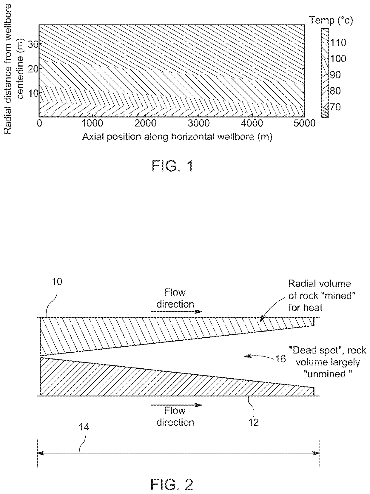
[0049]Referring now to FIG. 1, shown is a thermal illustration depicting the temperature tapering along the axial position of the horizontal well for a given surrounding rock volume. Noteworthy is the fact that there is a heating of the working fluid from the heel of the well to the toe. Heat transfer from the rock is inversely proportional to this working fluid temperature. Accordingly, most of the heat energy is captured at a maximum of the heel and a minimum of the toe. This obviously has efficiency limitations, since maxima and minima are created.

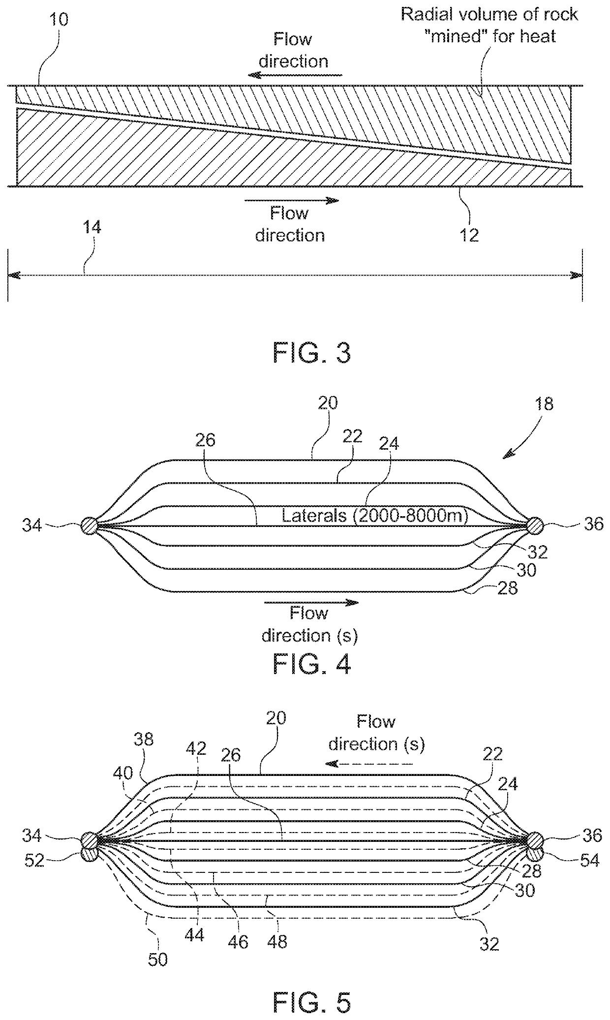
[0050]Referring now to FIG. 2, shown is a plan view of two spaced apart horizontal wellbores 10 and 12 disposed within a geothermal formation 14. The wells 10 and 12 are spaced apart but remain in thermal contact. Each wellbore 10 and 12, in this example, has a working fluid flow in the same direction as identified in the Figure. The thermal profile, as discussed with reference to FIG. 1 is depicted for each wellbore 10 and 12, with the...


PUM


Abstract

A method for controlling temperature maxima and minima from the heel to toe in geothermal well lateral sections. The method includes disposing at least a pair of wells proximately where thermal contact is possible. Working fluid is circulated in one well of the pair in one direction and the working fluid of the second well is circulated in as direction opposite. to the first. In this manner temperature equilibration is attainable to mitigate maxima and minima to result in a substantially more uniform temperature of the working fluids in respective wells and the rock formation area there between. Specific operating protocol is disclosed having regard to the temperature control for maximizing thermal energy recovery.

Description

FIELD OF THE INVENTION[0001]The present invention relates to thermal control of absorbed thermal energy in wells and more, particularly, the present invention relates to control of temperature dissipation and efficient energy recovery in geothermal wells, and optimization of the design and operation of closed-loop geothermal wellbore systems.BACKGROUND OF THE INVENTION[0002]Currently, the United States is a global leader in installed geothermal capacity having more than 3,300 megawatts in eight states. The majority of this is located in California.[0003]As is known, in geothermal energy heat is continually generated within the magma layer through radioactive decay. It has been reported that the amount of heat within 10,000 meters of Earth's surface contains 50,000 times more energy than all the oil and natural gas resources in the world. Clearly, this is a point of interest within the energy developer community.[0004]At these depths, issues were previously reported concerning the hi...

Claims


Application Information

Patent Timeline
Patent Type & Authority Patents(United States)
IPC IPC(8): F24T10/13F03G7/04
CPCF24T10/13F03G7/04F24T10/20E21B43/30E21B43/305E21B43/162F24T10/10F24T2201/00Y02E10/10F24T2010/56
Inventor CAIRNS, PAULTOEWS, MATTHEWREDFERN, JOHN
Owner EAVOR TECH INC
Why Eureka
Try Eureka