
A solar energy capture, energy conversion and energy storage system

Active Publication Date: 2020-10-22
FUTURE ENERGY SOURCE LTD
View PDF0 Cites 0 Cited by
  • Summary
  • Abstract
  • Description
  • Claims
  • Application Information

AI Technical Summary

Benefits of technology

The present invention maximizes solar energy extraction and optimizes subsequent energy usage and storage. It does not concern itself with cooling or pumping a working fluid in different orientations or limited space. Instead, it uses organic substances as a working fluid, which eliminates problems of needing to superheat and avoiding corrosion. Additionally, it offers the benefits of a single-stage expander instead of complex and expensive turbines.

Problems solved by technology

The solar collector was suitable for use for heating of CO2 in the cycle up to around 165° C. However, these solar thermal power generators used thermo fluids, such as chlorofluorocarbons (CFCs) and hydrofluorocarbons (HCFCs), which had a negative impact on the environment.
However, PV panels have some drawbacks.
For instance, PV panels are expensive and have limited efficiency levels ranging from around 12% to 20%.
Moreover, conversion of direct electric current (DC) generated from solar PVs to alternating current (AC) requires inverters and other expensive electronic equipment.
Another disadvantage with PV panels is that planning permission is often required in some jurisdictions in order to install the panels as they can have a visual impact in areas where architectural integrity is required.
A further drawback with PV panels is that they can become detached in very windy conditions and consequently can cause damage to property and persons.

Method used


Image

  • A solar energy capture, energy conversion and energy storage system
  • A solar energy capture, energy conversion and energy storage system
  • A solar energy capture, energy conversion and energy storage system

Examples


Embodiment Construction

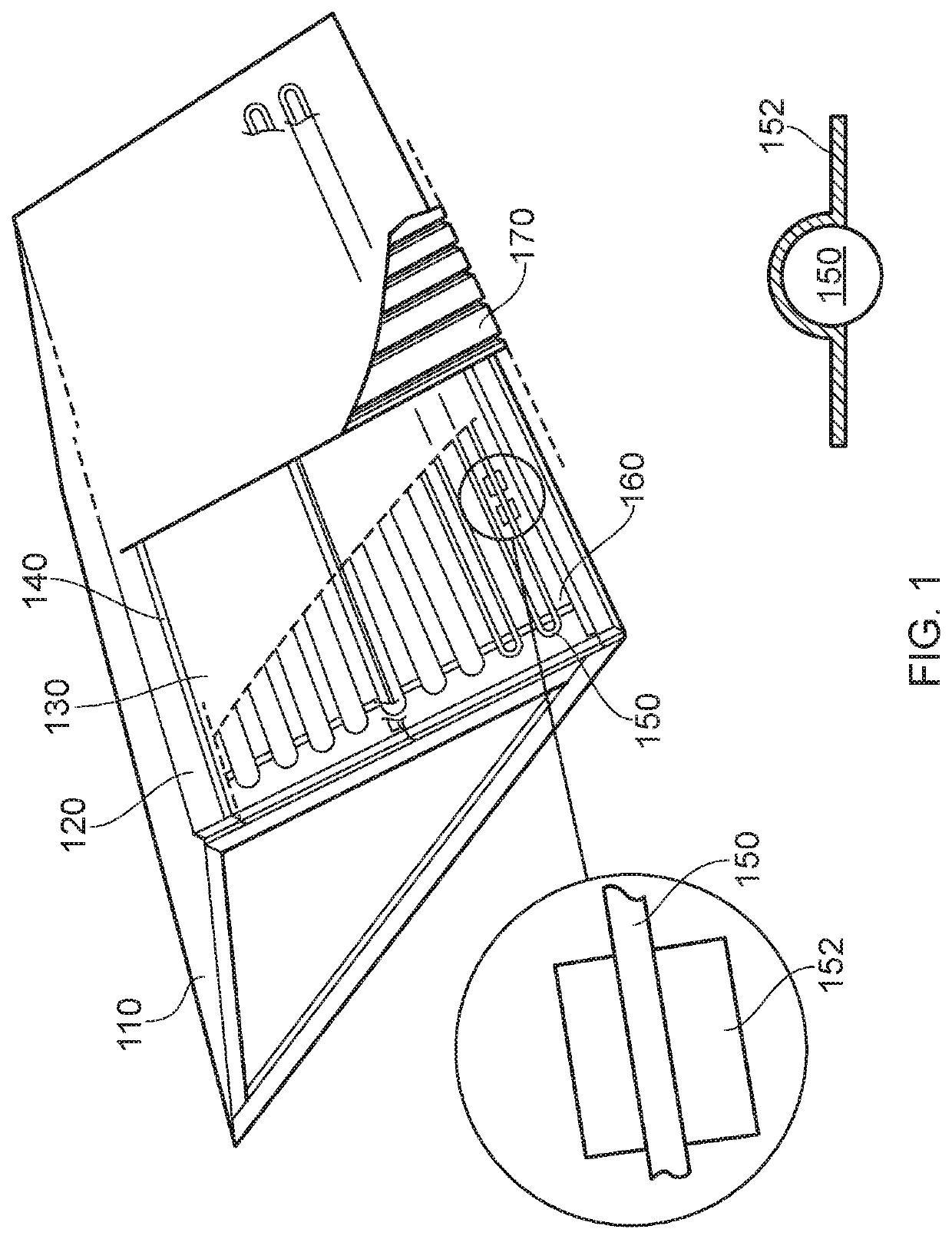
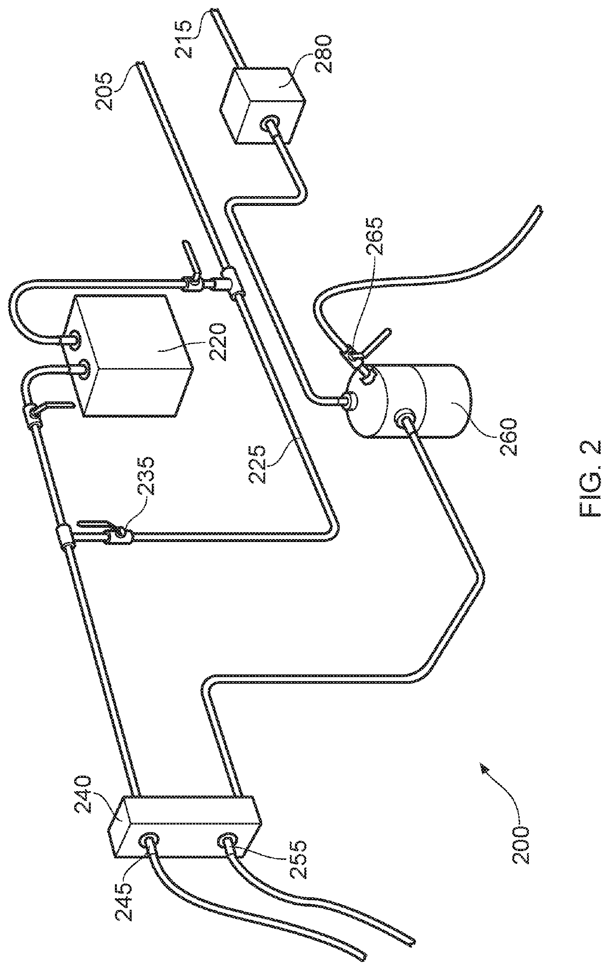
[0073]Referring to the Figures generally, there is shown in FIGS. 1 and 2 an example of a solar energy capture and conversion system comprising a solar collector 100 and a combined heat and electrical generating system 200.

[0074]FIG. 1 shows a flat plate solar collector 100 which comprises a mounting structure which supports a matrix 130 in which is embedded a conduit 150 containing a thermos-efficient working fluid which includes at least one hydro-fluoro-ether.

[0075]The mounting structure comprises a frame 110, a layer of insulation 120, a plurality of Z-purlins 140, an absorber plate 170 and a sheet of glazing (not shown). The bases of the Z-purlins 140 are supported on the frame 110 and the absorber plate 170 is supported on the upper surfaces of the Z-purlins 140. The sheet of glazing is supported on the absorber plate 170 and the insulation 120 and the matrix 130 are arranged between the frame and the absorber plate 170. The solar collector 100 has a layered structure; the fra...


PUM


Abstract

A solar energy capture, conversion and storage system for use on a roof of a building for capturing and converting incident solar radiation to heat and electricity. The invention provides an optimised solar energy capture and conversion system that monitors immediately available incident radiation comprising a mounting structure which supports a matrix in which is embedded a conduit containing a working fluid. The fluid or fluid mixture includes at least one hydro-fluoro-ether (HFE). Valves are arranged to open / close ports which connect the solar energy capture system to either a combined heat / electrical generating system or an energy storage system that incorporates a phase change material to store heat energy. Control of the valves is supervised by an energy management system.

Description

FIELD[0001]This invention relates to a solar energy capture, energy conversion and energy storage system. More particularly, but not exclusively the invention relates to a solar energy capture, storage and conversion system adapted to be supported on a roof of a building and to convert incident solar radiation to heat energy and to store latent heat for the purposes of heating and generation of electricity.BACKGROUND[0002]Fossil fuels are still the main source of energy for human activities. However, it is now generally accepted that use of fossil fuels has many adverse impacts on the environment. For instance, the release of large quantities of CO2 (a major greenhouse gas) is believed to be a cause of a rise in global surface temperature. Concerns also arise as to security of supply of fossil fuels and when fossil fuels will eventually be depleted.PRIOR ART[0003]Parabolic trough collectors are considered as one of the most viable solar energy capture systems. These are typically em...

Claims


Application Information

Patent Timeline
IPC IPC(8): F24S10/75F24S80/20F24S60/10F24S80/60F24S80/50F28D20/02F03G6/00F24S10/70
CPCF28D20/021F24S10/755G06Q50/06F24S80/60F24S60/10F24S80/50G06Q30/0202F03G6/003F24S2080/03F24S80/20F24S2010/751F28F1/14F03G6/065Y02E10/44Y02E70/30Y02B10/20Y02E10/46Y02E60/14F24S10/70F03G6/066F03G6/004
Inventor CAMFIELD, TONYKHAN, ZULFIQAR AHMADHELVACI, UTKUKHAN, ZAKIR
Owner FUTURE ENERGY SOURCE LTD
Learn More