Connecting assembly comprising a connecting piece and at least two bearers
a technology of connecting parts and bearers, which is applied in the direction of rod connection, sheet joining, aircraft components, etc., can solve the problems of promoting certain mechanical failure modes and encouraging premature breakage of components
- Summary
- Abstract
- Description
- Claims
- Application Information
AI Technical Summary
Benefits of technology
Problems solved by technology
Method used
Image
Examples
third embodiment
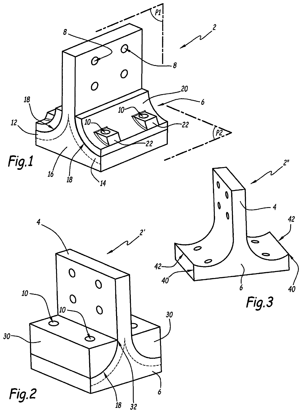
[0057]FIG. 3 depicts a connecting piece 2″ of a connecting assembly according to the invention. Those elements of this connecting piece which are analogous to the component 2 bear the same references and are not described in detail, in so far as the above description can be reapplied to them.
[0058]The component 2″ notably differs from the component 2 in that the curved extensions 18 end in a turned up curved portion 40 which forms an end stop 42 away from the main part 4.
[0059]This arrangement prevents the bearers 20 or 30 from slipping out of the receiving zone during phases of assembly of the connecting assembly and also when the component 2 is loaded. Specifically, in the event of loading on the wall 4, the expanses 2 and 14 have a tendency to be moved away from the base 6 at the bearers 20, which may cause undesirable movement of the bearers 20 if there is an assembly clearance. The end stop 42 therefore allows the washer to be held in place, improving the reaction of load by th...
fourth embodiment
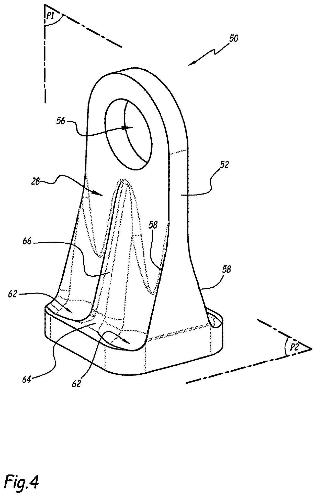
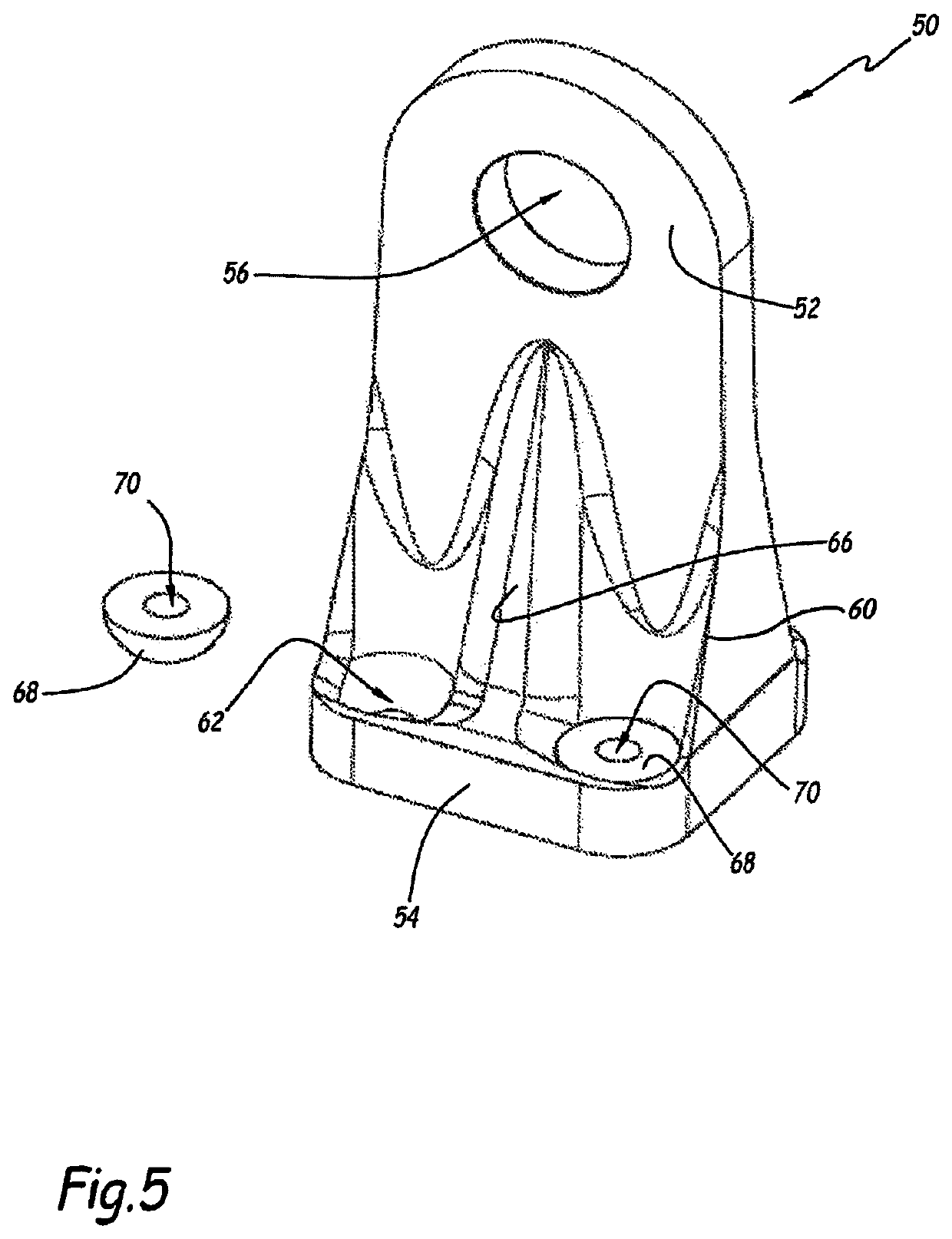
[0060]FIGS. 4 and 5 depict a connecting assembly according to the invention, which comprises a connecting piece 50 made of composite material, analogous to the component 2, for which the above description can be reapplied, with the exception of the differences in shape.
[0061]In particular, the component 50 comprises a main wall 52, also referred to as web, which extends out in a first geometric plane P1 from an upper face of a base 54 of the component 50, between a first end anchored to the base 54 and a free end that forms an upper part of the component 50. The free end of the wall 52 here has the shape of an arc of a circle or, more generally, a curved shape.
[0062]The base 54 extends in a second geometric plane P2 essentially perpendicular to the first plane P1 and defining two opposing branches one on each side of the main wall. The component 50 here also has a T shaped cross section. The plane P1, which here is vertical, forms a plane of symmetry of the component 50.
[0063]The wa...
fifth embodiment
[0078]FIG. 6 depicts a connecting assembly according to a Those elements of this connecting assembly which are analogous to the previous embodiments bear the same references and are not described in detail, in so far as the above description can be reapplied to them.
[0079]The connecting assembly comprises a connecting piece 80 made of composite material as described hereinabove, the component 80 performing a similar function to the components 2 and 50 to provide mechanical connection between first and second elements. The component 80 here also allows the attachment of a third element in addition to the first and second elements, as explained hereinafter.
[0080]The component 80 here comprises two walls 82, here identical to one another and analogous to the walls 4, and a flat base 84 from which the walls 82 extend. The walls 82 extend parallel to a plane P1 and the base 84 extends essentially parallel to a plane P2, these planes being analogous to the planes P1 and P2 defined herein...
PUM
 Abstract
Description
Claims
Application Information
 - R&D
- Intellectual Property
- Life Sciences
- Materials
- Tech Scout
- Unparalleled Data Quality
- Higher Quality Content
- 60% Fewer Hallucinations
Browse by: Latest US Patents, China's latest patents, Technical Efficacy Thesaurus, Application Domain, Technology Topic, Popular Technical Reports.
© 2025 PatSnap. All rights reserved.Legal|Privacy policy|Modern Slavery Act Transparency Statement|Sitemap|About US| Contact US: help@patsnap.com


