Torque limiting device

a torque limiter and torque technology, applied in the direction of wellbore/well accessories, slip couplings, couplings, etc., can solve the problems of additional problems in wellbore cleaning operations, string differential drag along its length, and cost-intensive intervention to repair or recover damaged strings, so as to reduce the risk of torque related damage and less resistance to torque

Active Publication Date: 2013-06-06
WEATHERFORD U S INC
View PDF12 Cites 7 Cited by
  • Summary
  • Abstract
  • Description
  • Claims
  • Application Information

AI Technical Summary

Benefits of technology

[0056]The torque limit setting of the torque limiting device is typically set to disengage and allow relative rotation of the components on opposite sides of the torque limiting device before the torque in the work string approaches the limits of the portion of the string below the torque limiting device, typically the wash pipe or other fishing tool, which typically has less resistance to torque than the drill pipe or other tubular above the torque limiting device. Therefore the torque limiting device typically maintains the operating torque of the work string as a whole within the limits of the weakest component in the string, thereby reducing the risks of torque related damage to the weaker components even if torque above the limiting device occasionally rises above the operational limits of the lower string.
[0057]Optionally more than one torque limiting device can be incorporated into the string, for example 2, 3, 4 or more torque limiting devices can be incorporated into the string. Optionally the torque limiting devices can be spaced apart from one another in the string, or can be grouped together, or clusters of torque limiting devices can be grouped together (e.g. 2, 3, 4 or more adjacent devices per cluster) while the clusters are spaced apart along the string. O

Problems solved by technology

When a cleaning string is rotated by the powerful rig top drive to scrub the inner surface of the casing string, an operator must be careful to avoid applying too much torque to the cleaning string because it is common for high torque levels that can be applied by the top drive to damage the cleaning string, requiring costly intervention to repair or recover the damaged string.
Additional problems can arise in well bore cleaning operations because of the practice of circulating different cleaning fluids such as brine through the string at the bottom of the well in order to displace drilling mud or other lubricant from the annular space between the casing string and the cleaning string.
Such a string will therefore experience differential drag along its length.
The moving interface between the brine and the drilling mud as the mud is displaced upwards along the annulus results in additional complications for the operator, and the risks of exceeding the mechanical properties of the lower string are

Method used


Image

  • Torque limiting device
  • Torque limiting device
  • Torque limiting device

Examples


Embodiment Construction

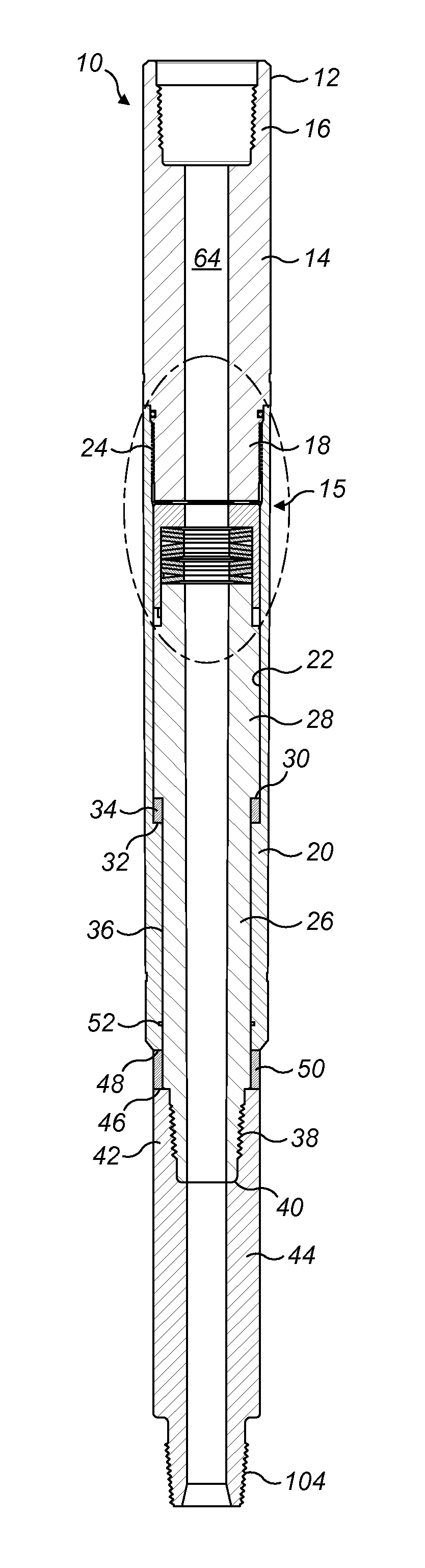
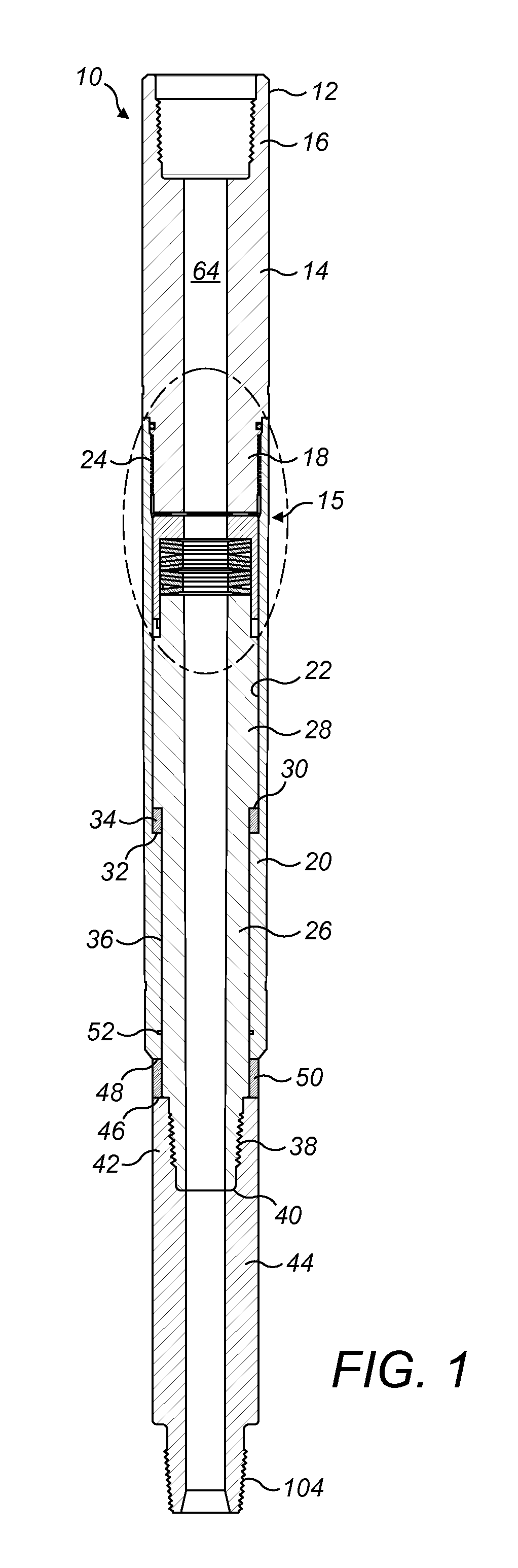
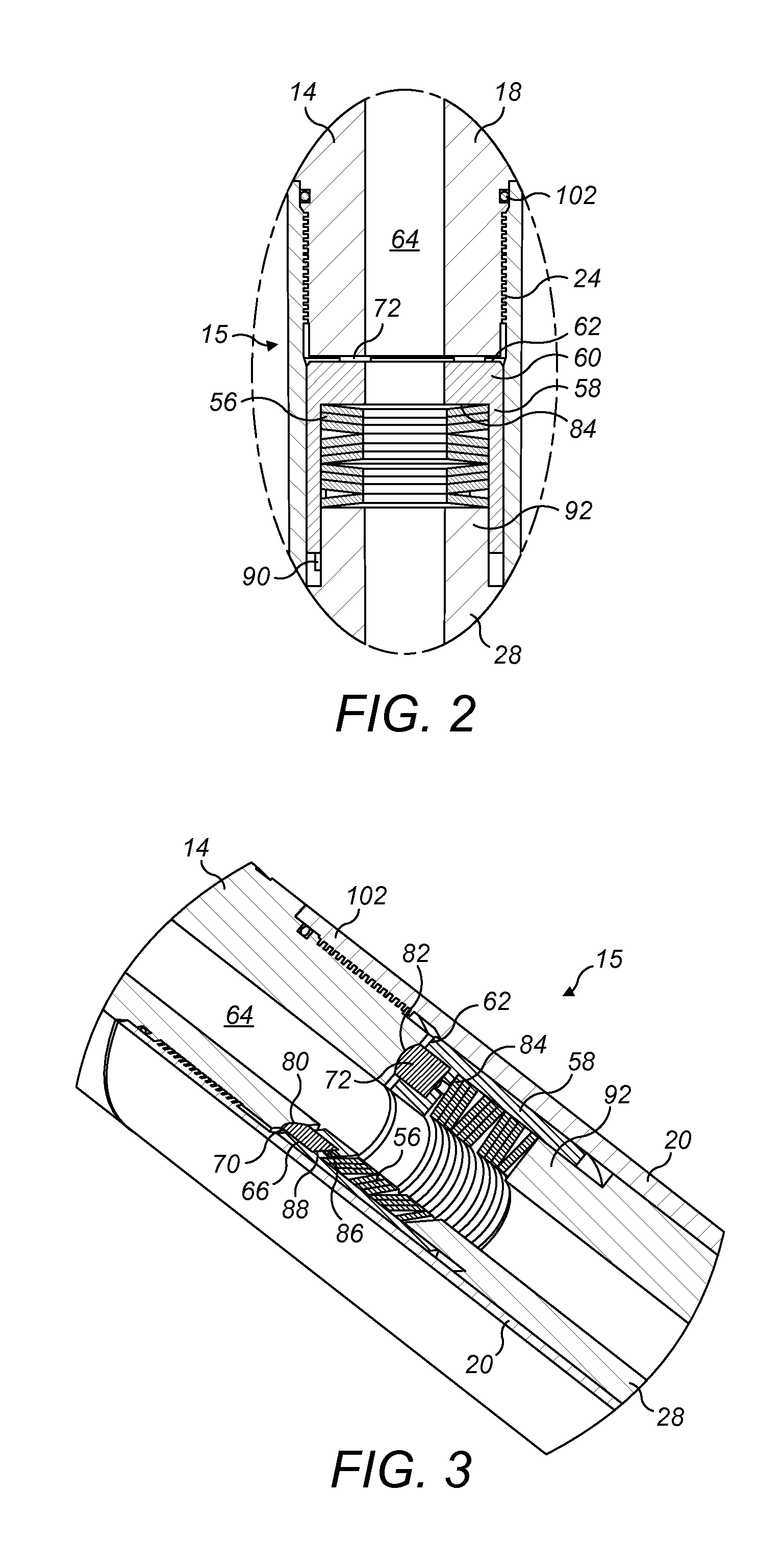
[0075]Various embodiments and aspects of the invention will now be described in detail with reference to the accompanying figures. Still other aspects, features, and advantages of the present invention are readily apparent from the entire description thereof, including the figures, which illustrates a number of exemplary embodiments and aspects and implementations. The invention is also capable of other and different embodiments and aspects, and its several details can be modified in various respects, all without departing from the spirit and scope of the present invention. Accordingly, the drawings and descriptions are to be regarded as illustrative in nature, and not as restrictive. Furthermore, the terminology and phraseology used herein is solely used for descriptive purposes and should not be construed as limiting in scope. Language such as “including,”“comprising,”“having,”“containing,” or “involving,” and variations thereof, is intended to be broad and encompass the subject m...


PUM


Abstract

A work string assembly for an oil or gas well has a first and second tubulars, and a torque limiting device connected in the work string. The torque limiting device has a body with an axial bore and two interconnected members that can disconnect to be relatively rotatable. The interconnected members can be repeatedly re-engageable when the torque levels drop below a torque threshold value, or can be connected by a frangible member that is broken when the interconnected members disconnect. A selectively actuable circulation port provided in the string adjacent to and above the torque limiting device allows the annulus between the work string and the casing to be flushed with fluid from the port.

Description

BACKGROUND OF THE INVENTION[0001]1. Field of the Invention[0002]The present invention relates to downhole tools and particularly, though not exclusively, to a torque limiting device used to allow relative rotation between two tubulars when a predetermined torque is applied between the tubulars, thereby reducing or preventing torsional damage to the tubulars or the connection between them at torque loads above the threshold of the predetermined torque.[0003]2. Description of the Related Art[0004]Wellbores typically contain various strings of tubulars connected end to end in the well. From time to time, for example, after drilling and casing a well, the inner surface of a tubular string such as a casing string is conveniently cleaned with a cleaning string to remove rust and other debris from the well bore. When a cleaning string is rotated by the powerful rig top drive to scrub the inner surface of the casing string, an operator must be careful to avoid applying too much torque to th...

Claims


Application Information

Patent Timeline
IPC IPC(8): E21B17/02
CPCE21B17/021E21B17/06E21B37/00F16D7/044E21B17/02E21B19/166E21B34/06
Inventor SULLIVAN, MICHAEL KEITHHART, SHANE PAULGLASER, MARK CHRISTOPHERCOOPER, RUAIRIDH
Owner WEATHERFORD U S INC
Why Eureka
Try Eureka