Supercharge Your Innovation With Domain-Expert AI Agents!

Pipe coupling apparatus

a pipe coupling and pipe joint technology, applied in the direction of mechanical devices, sleeves/socket joints, pipe joints, etc., can solve the problems of insufficient account for axial and/or radial expansion, cumbersome installation, and limited arrangement, so as to achieve the effect of sealing a joint between two pipes

Active Publication Date: 2021-12-07
FERNCO
View PDF45 Cites 1 Cited by
  • Summary
  • Abstract
  • Description
  • Claims
  • Application Information

AI Technical Summary

Benefits of technology

The apparatus effectively seals joints, maintains axial alignment, and accommodates radial forces, enabling the connection of pipes with varying diameters while being resistant to expansion and radial forces, thus improving the efficiency and versatility of pipe coupling.

Problems solved by technology

However, in some cases, the pipes being joined do not include boltable flanges.
However, these arrangements can be cumbersome to install due to the separate sheath that is wrapped around the gasket.
Moreover, this arrangement can be insufficient in accounting for axial and / or radial expansion of the gasket that may occur.
Additionally, such an arrangement may be limited to pipes having the same diameter due to the use of the sleeve that wraps around the gasket.
In some cases, a tapered intermediate pipe may be disposed between pipes having different diameters, but such pipes are more costly to produce and present an additional component that must be installed.

Method used


Image

  • Pipe coupling apparatus
  • Pipe coupling apparatus
  • Pipe coupling apparatus

Examples


Embodiment Construction

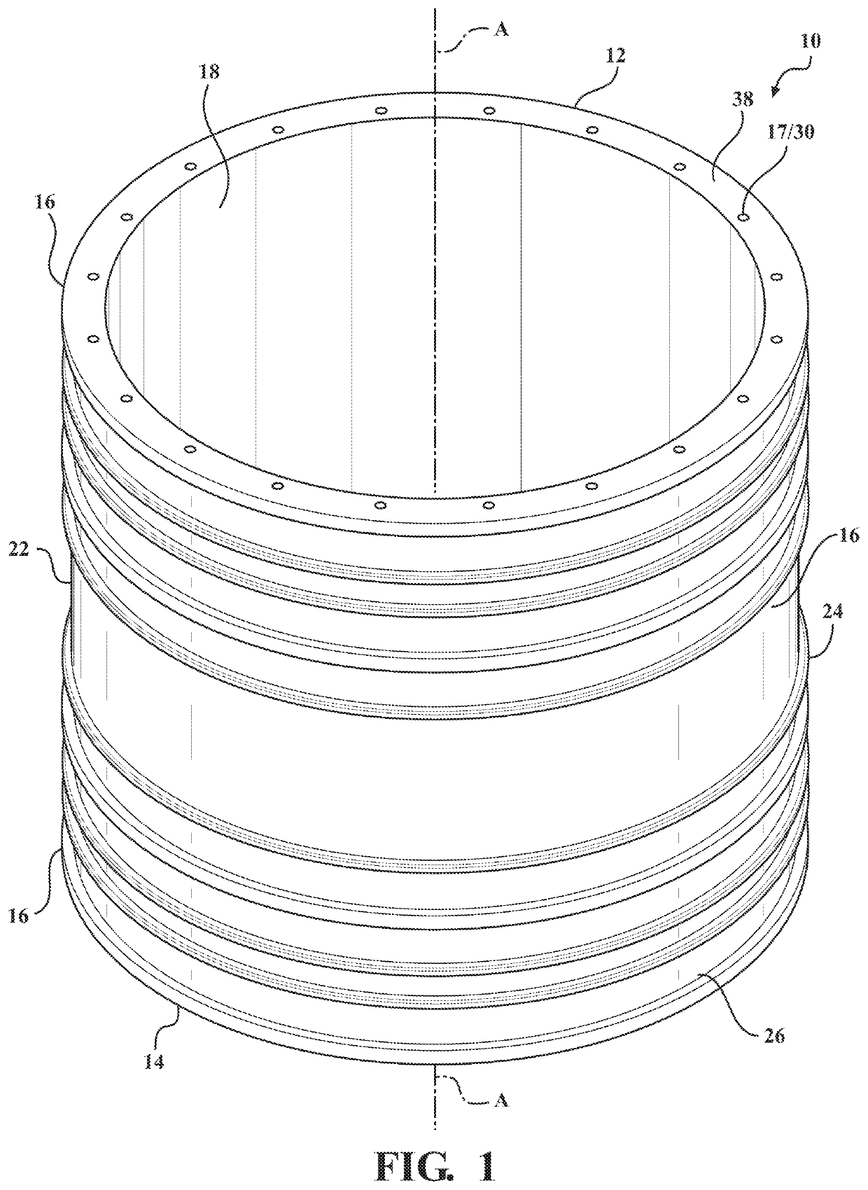
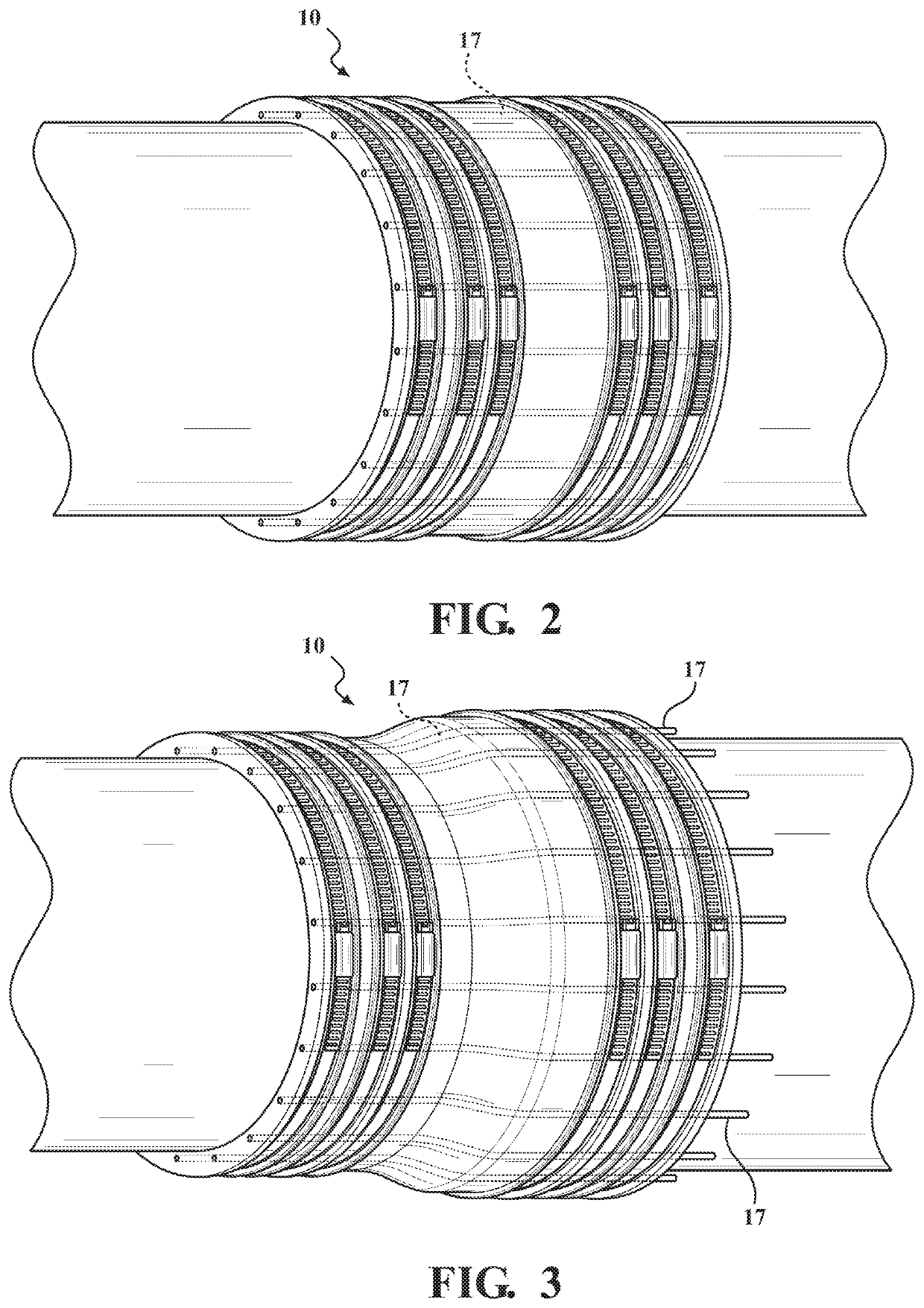
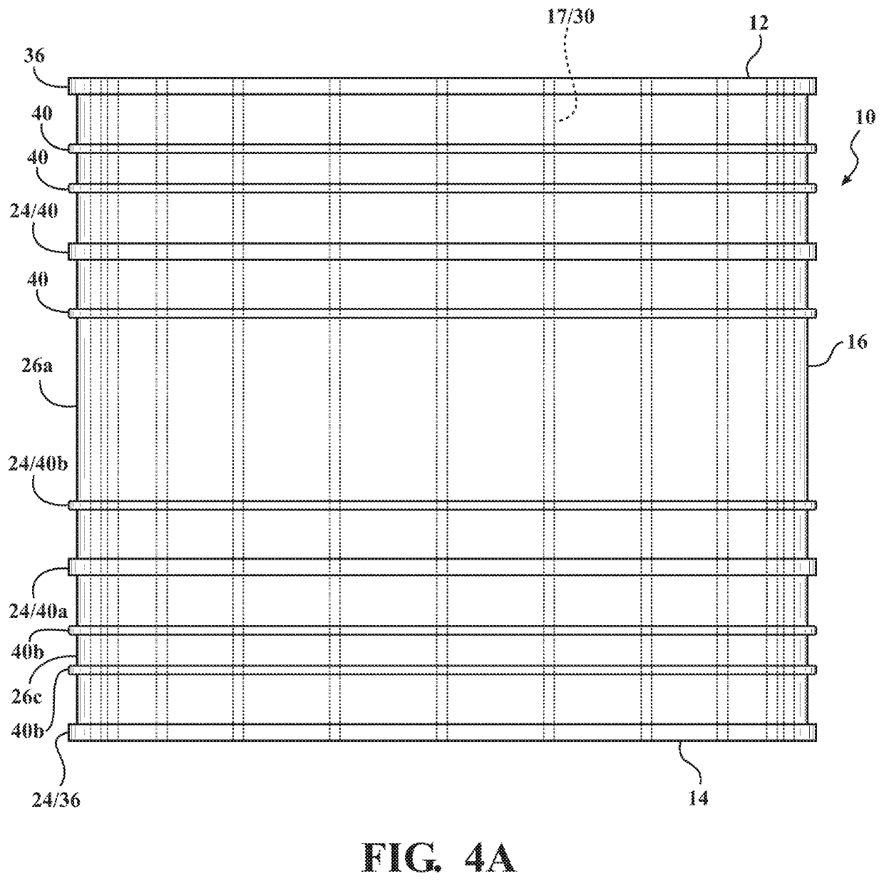
[0044]With reference to FIGS. 1 and 3-5, a pipe coupling apparatus 10 is generally shown and extends from a first end 12 to a second end 14 along a central axis A extending longitudinally through the center of the pipe coupling apparatus 10. The pipe coupling apparatus 10 includes a tubular body portion 16 extending between the first and second ends 12, 14. The pipe coupling apparatus 10 further includes a plurality of axially extending rods 17 disposed within the body portion 16.

[0045]The body portion 16 defines a passageway 18 extending therethrough. The passageway 18 is delimited by an inner surface 20. The body portion 16 is defined radially between the inner surface 20 and an outer surface 22. A plurality of annular flanges 24 extend radially outward from the outer surface 22. The annular flanges 24 define a plurality of annular recesses 26 surrounding the body portion 16.

[0046]The tubular body portion 16 has a generally tubular shape that extends along the axis A. The tubular ...


PUM


Abstract

A pipe coupling apparatus includes a flexible tubular body portion having a body portion a plurality of annular flanges projecting radially outward from the body portion and defining a plurality of annular recesses around the body portion. The body portion can be radially compressed at each end to different degrees, thereby allowing pipes with different diameters to be coupled. The body portion includes a plurality of rods disposed within the material of the body portion. When the ends of the body portion are compressed at different amounts, an intermediate portion of the body portion is tapered, and the rods bend. Clamp bands may be retained within the recesses and may provide the clamping force to radially compress the ends of the body portion to the desired amount.

Description

FIELD OF THE DISCLOSURE[0001]The present disclosure relates to pipe couplings. More particularly, the present disclosure relates to a flexible pipe coupling with a reinforcing structure.BACKGROUND OF THE DISCLOSURE[0002]Pipes are in common use, and are often used to provide for the conveyance of material such as various fluids, including water, gasoline, natural gas, waste / sewer or the like. Pipes may also be used to provide a conduit or passageway for other non-flowing tangible material, such as electrical cables or telecommunication wires.[0003]These pipes may be disposed in a variety of environmental conditions, both above ground and below ground. In many cases, pipes may be joined together in a butt-joint arrangement, with the ends of the pipes being brought together and joined. In some cases, the ends of the pipes include flanges that are bolted together, with a gasket ring disposed therebetween. In these cases, it is common for the pipes to have the same diameter and for the f...

Claims


Application Information

Patent Timeline
Patent Type & Authority Patents(United States)
IPC IPC(8): F16L21/00F16L21/06
CPCF16L21/002F16L21/06F16L25/14
Inventor DEWITT, DONALD JAMESDIPZINSKI, ANTHONY JOHN
Owner FERNCO
Features
  • R&D
  • Intellectual Property
  • Life Sciences
  • Materials
  • Tech Scout
  • Unparalleled Data Quality
  • Higher Quality Content
  • 60% Fewer Hallucinations
Learn More