Ball return assembly

a ball return and assembly technology, applied in the field of sports devices, can solve the problems of less portable and limited surface, less elasticity, and uneven ball return to the player, and achieve the effects of increasing elasticity, increasing elasticity, and different levels of elasticity

Active Publication Date: 2021-12-14
JOHNSON FRITZ
View PDF10 Cites 0 Cited by
  • Summary
  • Abstract
  • Description
  • Claims
  • Application Information

AI Technical Summary

Benefits of technology

[0008]This invention utilizes an elastic cord that is attached to a ball and is tethered to a base, and includes a net apparatus that receives the tethered ball and cord once the ball is hit or thrown. Unique to this invention is that the elastic cord is segmented with two or more segments that have different levels of elasticity. The elasticity increases along the length of the overall cord without doubling the cord, from the base to the ball. The preferred embodiment includes three cords of increasing elasticity connected end to end to form an overall cord that attaches the ball to the base. When the ball is hit over the net apparatus, the cord tension pulls the ball under the net apparatus while still maintaining tension. The cord wraps around the net apparatus and the ball strikes the side of the net facing the player. The ball then swings back under the net apparatus and back to the player. Once the ball bounces back to the player, the player then hits the ball again with his or her racket over the net apparatus and the process begins again. The increasing elasticity of the overall cord, along with the design of the net apparatus, provides for timing, bounce, and velocity of a ball return that simulates real play. The net apparatus includes an adjustable launch panel that varies the ball return trajectory and timing, and is designed in such a way as to simulate tennis court visuals with appropriate colors, netting, and height adjustment.

Problems solved by technology

The problem with these inventions is that the ball returns too quickly or chaotically to the player, and they do not simulate realistic playing conditions.
Also, bases in these inventions require adding sand or water for weight, making these inventions less portable and surface limited.
With these inventions the player has difficulty achieving a repetitive, consistent ball return and therefore the player cannot develop muscle memory.
Also these devices result in players having to chase every errant shot, as they do not utilize a ball tethered to a base.

Method used


Image

  • Ball return assembly
  • Ball return assembly
  • Ball return assembly

Examples


Embodiment Construction

[0022]While the invention has been described in detail in the drawings and following description, It should be understood that only the preferred embodiment has been shown. The use of a tennis ball for tennis practice is described herein. Other sports balls like those used for lacrosse, baseball, softball, racquetball, or cricket, for example, could also be used with this invention. Changes or modifications that come within the spirit of this invention are desired to be protected.

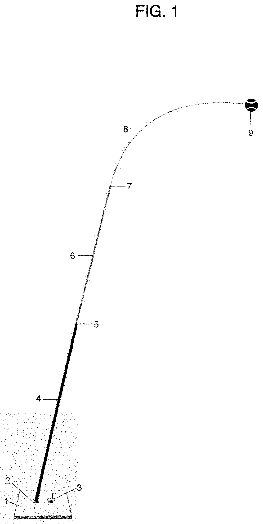
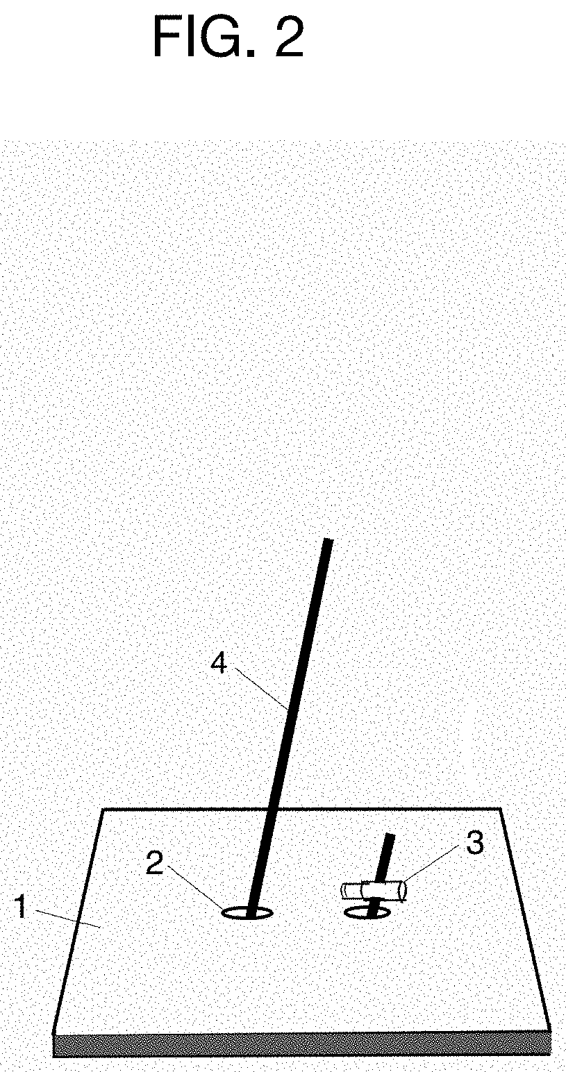
[0023]FIG. 1 illustrates the ball 9 tethered to the base 1. The base 1 is of such size and material as to not move once the ball 9 is struck. The preferred embodiment utilizes recycled tires for the base 1 material. The base 1, as shown in FIG. 2, includes two holes with rubber flanges 2 inserted, allowing the cord 4 to pass under the base 1. A cord lock 3 keeps the cord 4 secured to the base 1 and also allows for adjusting the length of the overall cord. A groove on the bottom of the base 1 can also be uti...


PUM


Abstract

A ball return assembly is configured to return a ball to a user. The ball return assembly has a base arranged on a ground surface with a first opening and a second opening. An elastic cord is threaded through the first opening and the second opening. A cord lock is joined to the cord first end, preventing the cord from being pulled from the base. A ball is joined to the cord. A frame is arranged proximate the base. The ball, upon contacting the frame, is pulled by the cord toward the base.

Description

RELATED APPLICATION[0001]This Application claims priority to provisional patent application U.S. Ser. No. 62 / 830,494 filed on Apr. 7, 2019.[0002]This application claims priority to provisional patent application U.S. Ser. No. 62 / 827,111 filed on Mar. 31, 2019 (the “'111 application”).[0003]The entire contents of the '494 application and the '111 application are herein incorporated by reference.BACKGROUND OF THE INVENTION[0004]This invention relates to sports devices and in particular to sports devices wherein a ball is returned to a player. The device is in the form of a tethered ball return game. The preferred embodiment utilizes a tennis ball, but other sports balls could also be used. Thus, although tennis practice is the focus of the embodiment herein, it should be understood that other sports such as lacrosse, baseball, softball, racquetball, and cricket could utilize this invention.[0005]Various tennis trainers have been manufactured that include a tennis ball on a cord tether...

Claims


Application Information

Patent Timeline
Patent Type & Authority Patents(United States)
IPC IPC(8): A63B69/00A63B63/00
CPCA63B69/0097A63B63/00A63B69/0079A63B2063/001A63B2209/00A63B2225/09A63B2210/50A63B71/023A63B2225/093A63B69/38A63B61/003
Inventor JOHNSON, FRITZ
Owner JOHNSON FRITZ
Why Eureka
Try Eureka