
Plate carrier absorption of shock from movement of wearer

a plate carrier and wearer technology, applied in the direction of protective equipment, weapons, protective garments, etc., can solve the problems of plate sliding or movement within, affecting balance or otherwise and achieve the effect of reducing impact or other forces, affecting balance, and negatively affecting the wearer

Active Publication Date: 2022-02-08
5 11 INC
View PDF165 Cites 1 Cited by
  • Summary
  • Abstract
  • Description
  • Claims
  • Application Information

AI Technical Summary

Benefits of technology

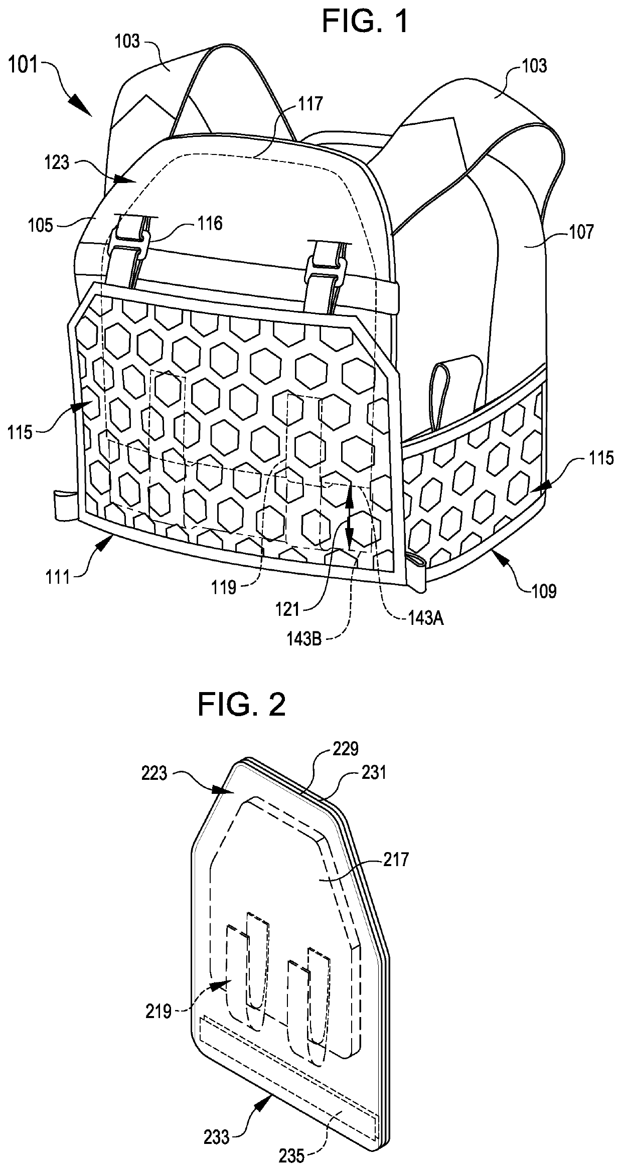
[0005]Embodiments herein are directed to plate retention systems in a plate carrier. The plate retention systems can include suitable support features for shock absorption against plate movement caused by movement of the wearer. For example, in use, a wearer of a plate carrier may undergo significant amounts of physical exertion, such as during tactical scenarios or in athletic settings. Movement of the wearer of the plate carrier can result in jostling or movement of the plate within the pocket of the plate carrier. In some situations, movement of the plate may exert uncomfortable forces or effects on the wearer, such as from the plate bouncing against the wearer or exerting momentum against the wearer, which may affect balance or otherwise negatively affect the wearer. Generally, support features disclosed herein provide secure support for a plate in a plate carrier, yet the support system is flexibly resilient to provide shock absorption for the plate and reduce impact or other forces exerted by the plate on the wearer of the plate carrier.
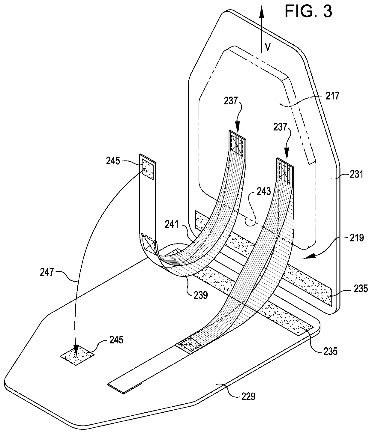
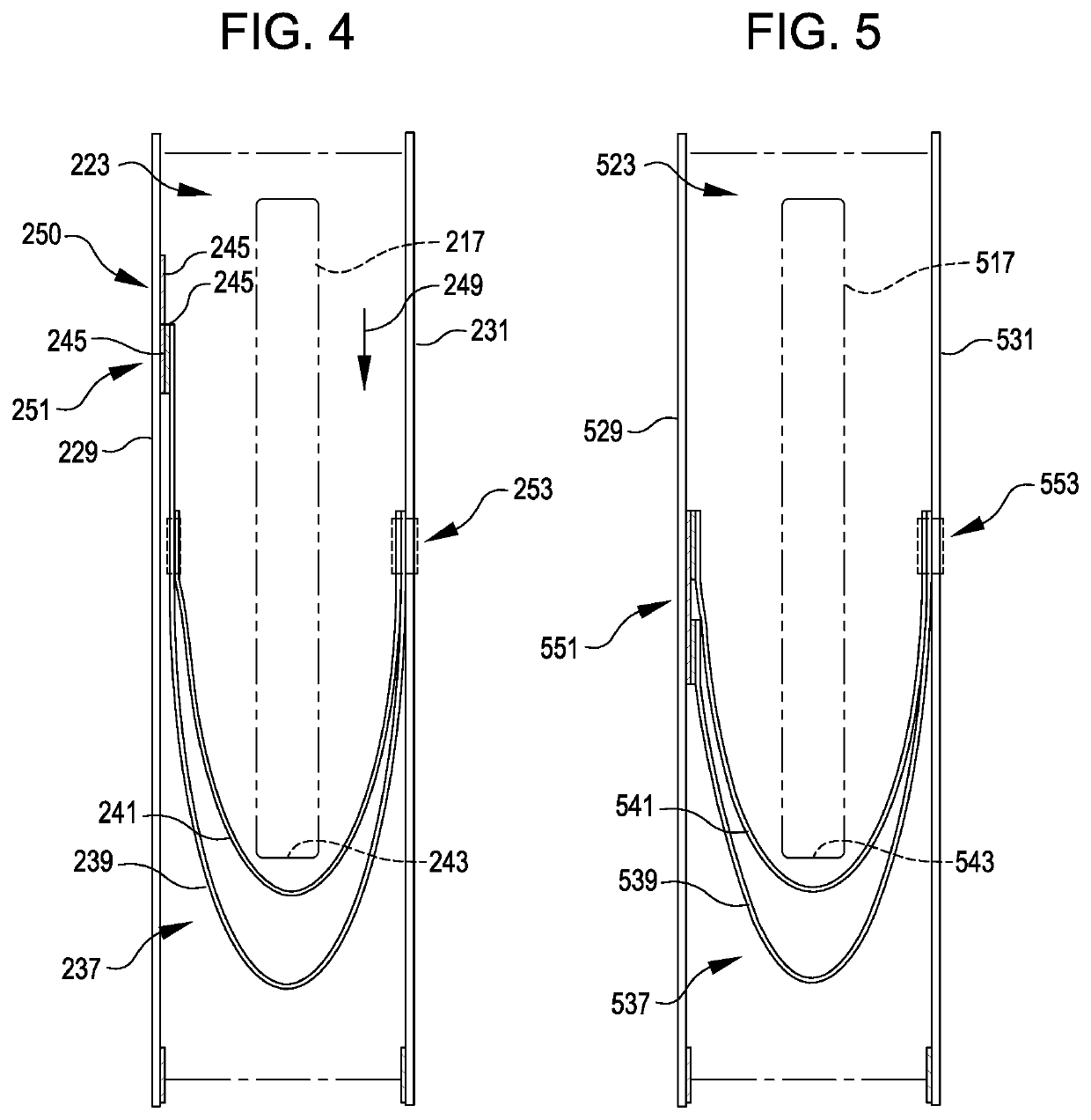
[0006]In various examples, the plate carrier includes a cradle with straps that wrap underneath an underside or lowermost edge of a plate within the pocket. Some part of the cradle (such as a part of a strap or of an anchor point) may include material that is more stretchable than other material of surrounding elements in the plate carrier, such as a pocket wall, a different part of the strap, or a separate strap. The difference in stretch capacity of different parts of the plate carrier can enable some parts to readily stretch under load to facilitate shock-absorption while other parts remain relatively stable under load to provide complementary appropriate bounds to the shock-absorption to ensure suitable overall securing of the plate within the plate carrier.
[0007]In some examples, the cradle includes a set of support straps that includes a limit strap and a shock-absorption strap. The shock-absorption strap can hang down in a loop spaced over another loop formed by the limit strap. In use, the bottom edge of the plate can rest against the shock-absorption strap. The movement of the wearer may cause movement of the plate that causes the shock-absorption strap to stretch and then return based on the resilience of the shock-absorption strap. In effect, this may absorb energy that the plate is transferring due to movement. The limit strap beneath the shock-absorption strap may provide a lowermost limit for the plate to ensure that the plate does not reach a position or a level of deflection of the shock-absorption strap that may cause damage or failure of the shock-absorption strap.
[0008]The cradle may include other arrangements of combinations of materials having differing levels of stretch, elongation, and / or recovery. As one example, the cradle may include stretchable material at an anchor point of a support strap to allow the support strap to move and provide shock absorption. The support strap and / or pocket wall may include a relatively less stretchable material that may retain the plate in place when the wearer is not causing movement of the plate carrier.

Problems solved by technology

Movement of the wearer of the plate carrier can result in jostling or movement of the plate within the pocket of the plate carrier.
In some situations, movement of the plate may exert uncomfortable forces or effects on the wearer, such as from the plate bouncing against the wearer or exerting momentum against the wearer, which may affect balance or otherwise negatively affect the wearer.

Method used


Image

  • Plate carrier absorption of shock from movement of wearer
  • Plate carrier absorption of shock from movement of wearer
  • Plate carrier absorption of shock from movement of wearer

Examples


Embodiment Construction

[0021]In the following description, various embodiments will be described. For purposes of explanation, specific configurations and details are set forth in order to provide a thorough understanding of the embodiments. However, it will also be apparent to one skilled in the art that the present invention may be practiced without the specific details. Furthermore, well-known features may be omitted or simplified in order not to obscure the embodiment being described.

[0022]Referring now to the figures in which features identified with like numbers may refer to like elements across the various figures, FIG. 1 illustrates a plate carrier 101 according to various embodiments. The plate carrier 101 in FIG. 1 is depicted with a form factor of a vest. However, the plate carrier 101 may equally correspond with other forms of bodily-worn garments. For example, features of the plate carrier described herein may equally apply to plates positioned to guard the torso of a wearer, or an appendage ...


PUM


Abstract

A plate carrier (such as a vest) is provided having shock absorption capabilities for absorbing shock in response to movement of a plate within the carrier resulting from movement of the wearer. The plate carrier can include a cradle that supports the plate within a pocket from underneath. Stretchable material may be incorporated into the cradle to provide shock absorption. For example, the cradle may include a limit strap hanging to form a first loop and a shock-absorption strap hanging to form a second loop spaced above the first loop. The shock-absorption strap may be formed from a material more stretchable than the limit strap, for example, so that the limit strap provides a limit of plate deflection and shock absorption provided.

Description

BACKGROUND[0001]Plate carriers may be utilized in many contexts. Often, plate carriers have a form factor of a vest, for example, including shoulder yokes that rest on a wearer's shoulders and support respective front and back panels that each include pockets for receiving plates. Such a plate is typically a generally rigid body (e.g., with an overall shape that is flat or at least partially curved) and may include ballistic material or non-ballistic material, depending on the context of use for the plate carrier.[0002]For example, for military, law enforcement, or other tactical contexts, a ballistic plate may be inserted and retained within a pocket in a plate carrier to provide protection for the wearer against injury from bullets or other projectiles. The pocket may allow for different sizes of plates, for example. Many plate carriers feature length-adjustable straps to secure different size plates such as large, medium, or small. This may allow for flexibility for a user to sel...

Claims


Application Information

Patent Timeline
Patent Type & Authority Patents(United States)
IPC IPC(8): F41H1/02A41D13/05A41D13/00F41H5/013
CPCF41H1/02A41D13/0002A41D13/0518A41D13/0593F41H5/013A41D13/0153
Inventor CIGARD, TYLERFUKUSHIMA, KATELYNPARK, SHARON
Owner 5 11 INC
Learn More