Surface acoustic wave filter and communication apparatus

a surface acoustic wave and filter technology, applied in electrical equipment, impedence networks, electric/electrostrictive/magnetostrictive devices, etc., can solve the problems of insufficient performance of differential amplifiers, increased insertion loss in the passband, and degraded degree of balanced signals

Inactive Publication Date: 2004-04-08
MURATA MFG CO LTD
View PDF11 Cites 9 Cited by
  • Summary
  • Abstract
  • Description
  • Claims
  • Application Information

AI Technical Summary

Benefits of technology

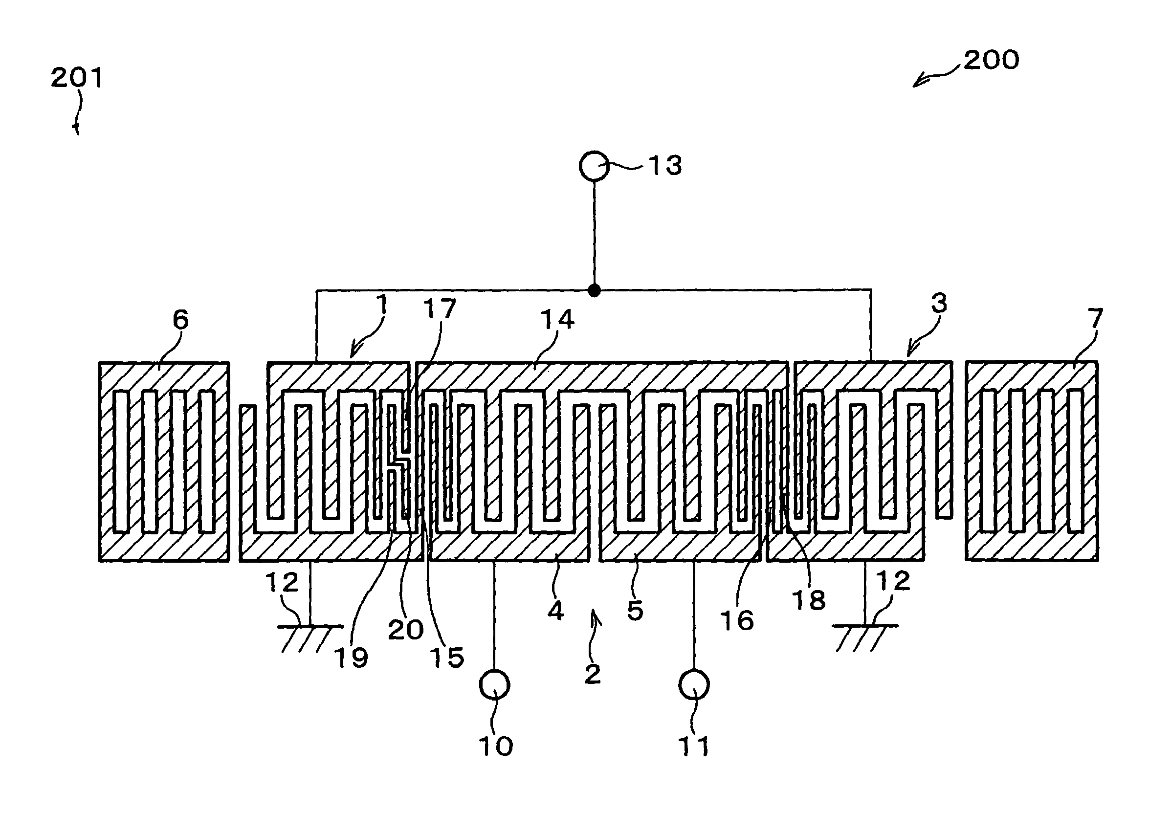
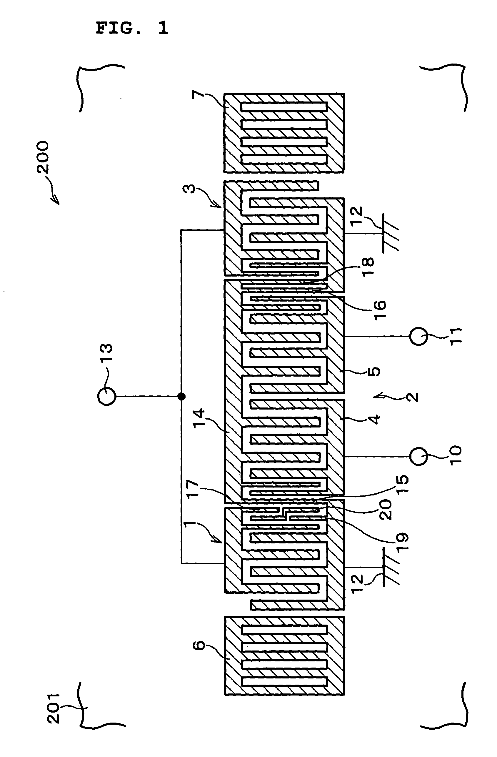
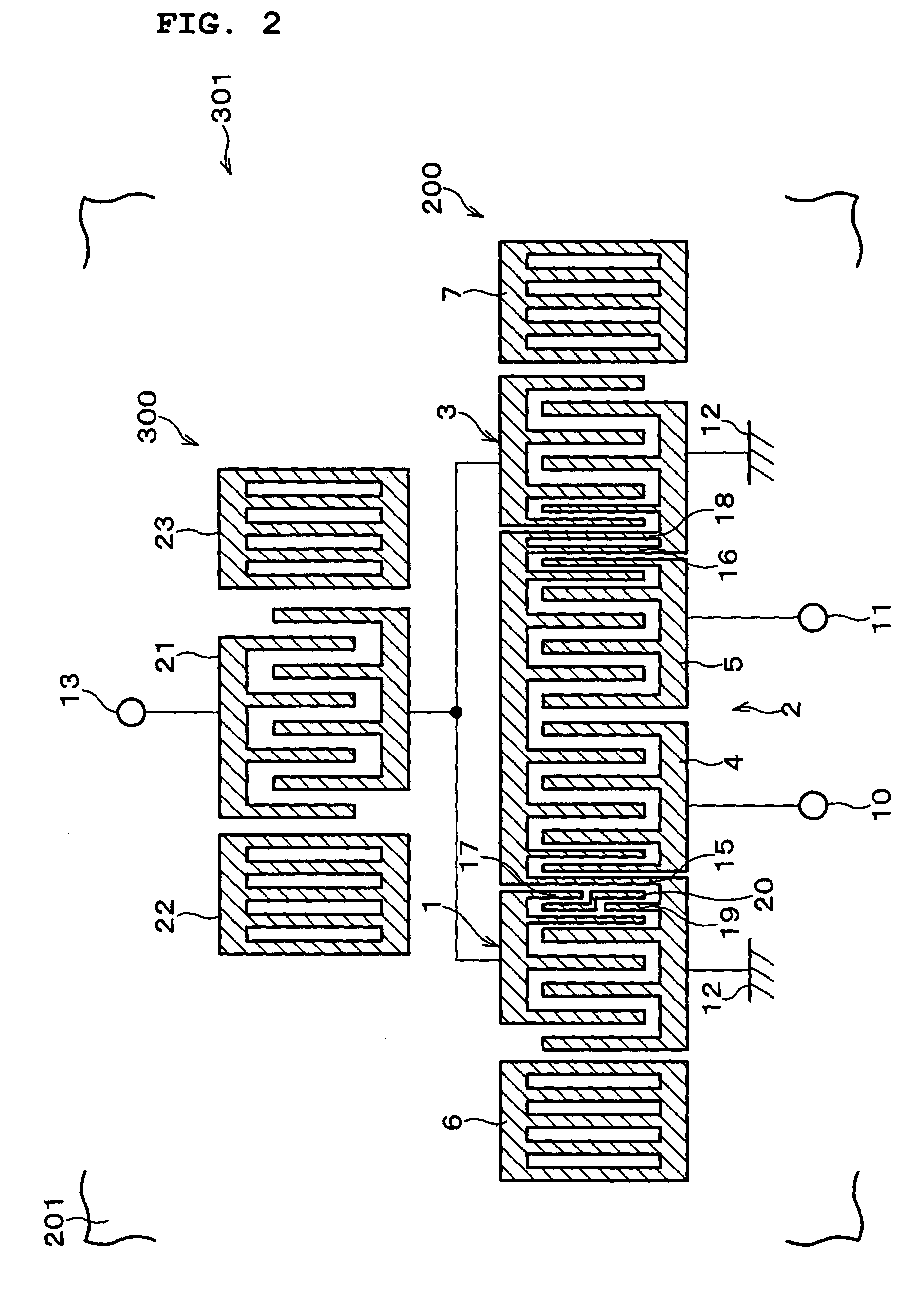
[0033] In the above-described arrangement, the output voltages of the two comb-like electrodes have greatly improved balance. The grounding of the serial junction produces the improved balance of the output voltages of the two comb-like electrodes which affects the degree of balance of the balanced signal terminals. Furthermore, with the serial junction joints grounded, electromagnetic shielding between the unbalanced terminal and the balanced terminals is reinforced. The direct-path wave from the unbalanced signal terminal to the balanced signal terminals is reduced. The grounding of the serial junction thus reliably improves the degree of balance of the balanced signals.

Problems solved by technology

If the degree of balance of the balanced signal input to the differential amplifier is poor, the differential amplifier has insufficient performance.
The construction of the surface acoustic wave filter 1000 shown in FIG. 9 increases insertion loss in the passband and degrades the degree of balance of the balanced signals.
The localization of currents in the electrode fingers in a particular area increases energy loss in the form of heat through the resistance of the electrode fingers.
If a line or an electrode pad is added to the piezoelectric substrate to ground the serial junction, a parasitic capacitance may increase which adversely affects the characteristics of the surface acoustic wave filter.

Method used


Image

  • Surface acoustic wave filter and communication apparatus
  • Surface acoustic wave filter and communication apparatus
  • Surface acoustic wave filter and communication apparatus

Examples


second preferred embodiment

[0058] A second preferred embodiment of the present invention will now be described with reference to FIG. 6. For convenience of explanation, elements that are identical to those described with reference to the first preferred embodiment are designated with the same reference numerals and the discussion thereof is omitted.

[0059] FIG. 6 illustrates a surface acoustic wave filter 400 of the second preferred embodiment. The surface acoustic wave filter 400 includes an IDT 1a instead of the IDT 1 used in the piezoelectric substrate 201 in the first preferred embodiment. The IDT 1a has a serial connection weighting between a second electrode finger and a third electrode finger from the IDT 2 rather than between the first and second electrode fingers in the IDT 1. A first electrode finger 30 closest to the IDT 2 has substantially the same length as the remaining electrode fingers. A third electrode finger 31 closest to the IDT 2 is approximately half the length of the remaining electrode ...

third preferred embodiment

[0061] A third preferred embodiment of the present invention will now be described with reference to FIG. 7. For convenience of explanation, elements that are identical to those discussed in connection with the first and second preferred embodiments are designated with the same reference numerals and the discussion thereof is omitted.

[0062] FIG. 7 illustrates a surface acoustic wave filter 500 in accordance with the third preferred embodiment of the present invention. The surface acoustic wave filter 500 includes an IDT 1b instead of the IDT 1a used in the piezoelectric substrate 201 in the first preferred embodiment. The IDT 1b is identical to the IDT 1a except that the electrode finger thereof closest to the IDT 2 is eliminated. The number of surface acoustic wave exciting regions of IDT 1b is less than that of the IDT 1 by two. Furthermore, the IDT 3 is replaced with an IDT 3b having one electrode finger that is approximately half the length of the other electrode fingers.

[0063] ...


PUM


Abstract

A surface acoustic wave filter includes a first reflector, a first IDT, a second IDT, a third IDT, and a second reflector arranged in that order on a piezoelectric substrate. The first IDT and the third IDT, connected in parallel, are together also connected to an unbalanced signal terminal. The second IDT includes two separate comb-like electrodes arranged in the direction of propagation of a surface acoustic wave, and electrically connected in series to each other at a serial junction. The comb-like electrodes are respectively connected to balanced signal terminals. The outermost electrode finger of the first IDT is connected to the unbalanced signal terminal, and the outermost electrode finger of the third IDT is grounded. The first IDT only or both the first IDT and the third IDT are weighted so that the number of excitation regions of the surface acoustic wave between the second IDT and the first IDT becomes equal to the number of excitation regions of the surface acoustic wave between the second IDT and the third IDT.

Description

[0001] 1. Field of the Invention[0002] The present invention relates to surface acoustic wave filters and, more particularly, to a surface acoustic wave filter having a balanced-unbalanced transformation function.[0003] 2. Description of the Related Art[0004] Technological advances in the miniaturization and light-weight design of communication apparatuses such as mobile telephones has been dramatic. As frequency of use increases, surface acoustic wave filters, which are relatively easy to miniaturize, are increasingly used in communication apparatuses. To reduce the number of electronic components and miniaturize the electronic components, efforts have been made to develop components which have a plurality of functions.[0005] Surface acoustic wave filters having a balanced-unbalanced transformation (a so-called balun transformation) function for use in RF stages of the mobile telephone have been actively studied, and are beginning to be used particularly in the GSM (global system f...

Claims


Application Information

Patent Timeline
Patent Type & Authority Applications(United States)
IPC IPC(8): H03H9/00H03H9/25H03H9/145H03H9/64
CPCH03H9/0038H03H9/02748H03H9/14588H03H9/14547H03H9/14582H03H9/14532H03H9/25
Inventor SHIBAHARA, TERUHISA
Owner MURATA MFG CO LTD
Why Eureka
Try Eureka