Nail screw

a nail screw and screw head technology, applied in the field of nail screws, can solve the problems of undesired wood split, and achieve the effect of simple unscrewing of the nail screw

Active Publication Date: 2022-02-15
RAIMUND BECK NAGELTECHNIK GMBH
View PDF14 Cites 0 Cited by
  • Summary
  • Abstract
  • Description
  • Claims
  • Application Information

AI Technical Summary

Benefits of technology

[0008]This special design of the nail screw causes the springback caused by material displacement when the nail screw is driven into a material and thus the pullout force of the nail screw to be increased as compared to the prior art nail screw. In addition, the inventive choice of the tip angle, more precisely a relatively blunt tip, prevents a splitting of the wood into which the nail screw is driven and thus leads to an improved optical appearance of a connection point as compared to the prior art nail screw. Furthermore, the double thread which can also be called a two-start thread results in a greater axial movement during one revolution as compared to a single threaded thread and thus the nail screw can be faster unscrewed from connected components.
[0012]In order to enable particularly smooth-running and simple unscrewing of the nail screw from components to be connected, in one exemplary embodiment the double thread has self-cutting thread flanks.

Problems solved by technology

The known nail screws have the disadvantage that when they are driven into wood, especially real wood, the wood splits undesirably.

Method used


Image

  • Nail screw
  • Nail screw

Examples


Embodiment Construction

)

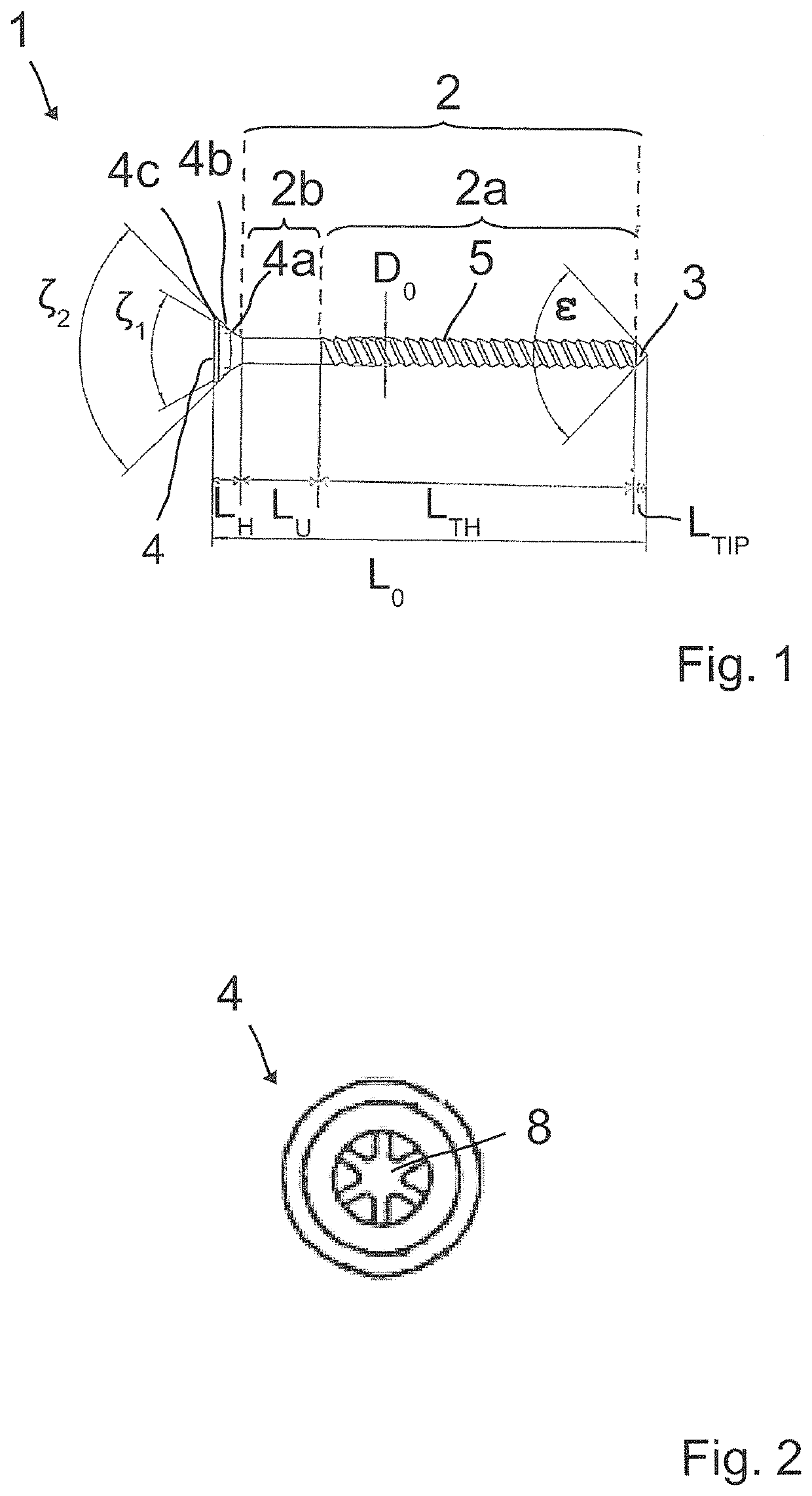
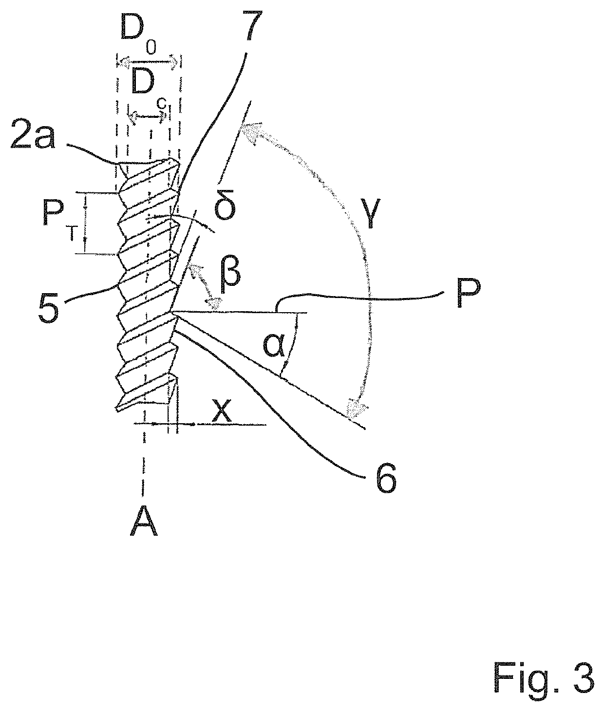
[0020]FIGS. 1 to 3 show a nail screw 1 for connecting facade boards or terrace planks made of real wood according to the invention. Nail screw 1 has a shaft 2, a conical tip 3 formed at the front end region of the shaft 2 and a head 4 formed at the rear end region of the shaft 2. A double thread 5 having a forward facing insertion flank 6 and a rearward facing grip flank 7 is provided on the shaft 2 between the conical tip 3 and the head 4. More precisely, the shaft 2 consists of a threaded shaft portion 2a which has the thread 5 and directly adjoins to the conical tip 3 and an unthreaded shaft portion 2b which is formed between the threaded shaft portion 2a and the head 4.

[0021]A grip flank angle α measured between the grip flank 7 and a plane P perpendicular to the longitudinal axis A of the nail screw 1 is 30 degrees in the present case. Furthermore, an insertion flank angle β measured between the insertion flank 6 and the plane P is 70 degrees in the present case. A resulting t...


PUM

PropertyMeasurementUnit
flank angleaaaaaaaaaa
tip angleaaaaaaaaaa

Abstract

A nail screw, in particular for connecting facade boards or terrace planks made of wood, especially real wood, has a shaft, a conical tip formed at the front end region of the shaft and a head formed at the rear end region of the shaft. A thread has a forward facing insertion flank and a rearward facing grip flank between the conical tip and the head. The thread is a double thread, wherein a grip flank angle (α) measured between the grip flank and a plane perpendicular to the longitudinal axis of the nail screw is between 25 and 35 degrees, more preferably between 28 and 32 degrees, most preferably 30 degrees. The conical tip has a tip angle (ε) between 80 and 120 degrees, more preferably between 90 and 110 degrees, most preferably of 80, 90 or 100 degrees.

Description

FIELD OF THE INVENTION[0001]The present invention relates to a nail screw, in particular for connecting facade boards or terrace planks made of wood, especially real wood, having a shaft, a conical tip formed at the front end region of the shaft and a head formed at the rear end region of the shaft, wherein a thread having a forward facing insertion flank and a rearward facing grip flank is provided on the shaft between the conical tip and the head.BACKGROUND OF THE INVENTION[0002]When it comes to joining components together, nails or screws are often used. A great advantage of nail connection is that they can be produced relatively quickly compared to screw connections. Screw connections, on the other hand, are relatively easy to unscrew compared to nail connections.[0003]Nail screws that combine the advantages of screws and nails have been available for some time now. Such nail screws can be driven into components to be connected by means of an automatic nail gun. The position of ...

Claims


Application Information

Patent Timeline
Patent Type & Authority Patents(United States)
IPC IPC(8): F16B25/00F16B25/10
CPCF16B25/106F16B25/0015F16B25/0068F16B25/0073F16B25/0047F16B25/0084
Inventor BECK, CHRISTIAN
Owner RAIMUND BECK NAGELTECHNIK GMBH
Why Eureka
Try Eureka